A line scan imaging device

An imaging device and line scanning technology, applied in the field of optical imaging, can solve problems such as difficult detection and imaging, complex devices and methods, and image degradation, and achieve the effects of reducing image reconstruction time, long detection distance, and enhanced mobility

Active Publication Date: 2018-09-14
TECHNICAL INST OF PHYSICS & CHEMISTRY - CHINESE ACAD OF SCI
View PDF4 Cites 0 Cited by
  • Summary
  • Abstract
  • Description
  • Claims
  • Application Information

AI Technical Summary

Problems solved by technology

[0005] During the sampling period, the relative motion between the target and the system will cause problems such as image degradation, making it difficult to achieve fast point detection imaging for moving targets
The existing motion compensation method is to perform translation compensation on the light field intensity distribution recorded by the reference arm detector, and the device and method are complicated and impractical
Generally speaking, the point detection imaging method currently researched is only suitable for imaging static targets or extremely low-speed targets, and point detection imaging for moving target imaging is still a hot spot and difficult point in current imaging research.

Method used


Image

  • A line scan imaging device
  • A line scan imaging device
  • A line scan imaging device

Examples


Embodiment 1

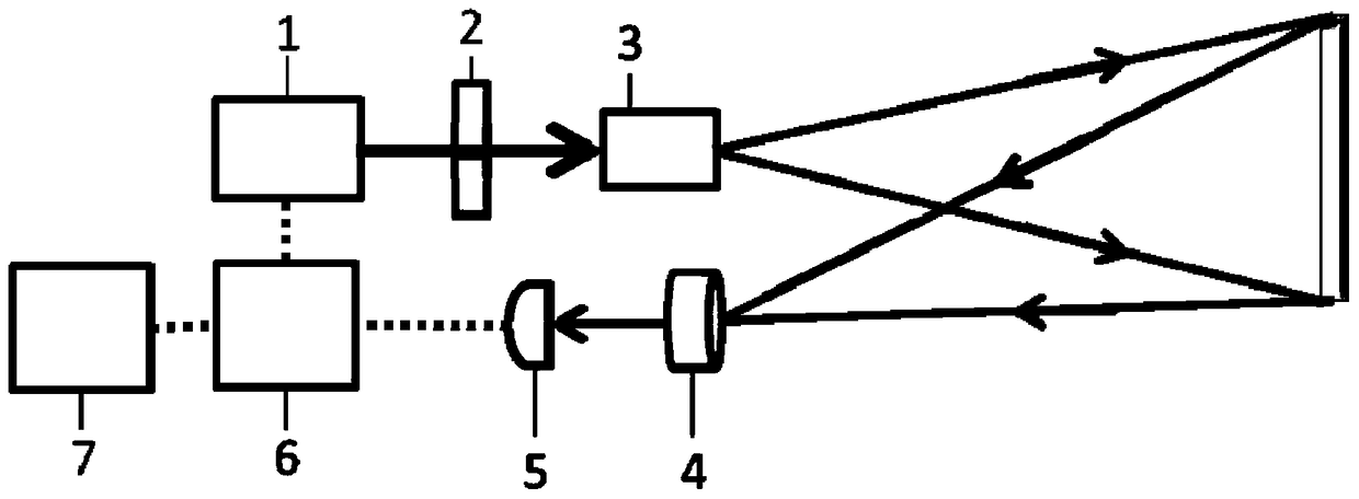
[0050] figure 1 It is a schematic structural diagram of a line scan imaging device according to a preferred embodiment 1 of the present invention, which includes a line laser source and an intensity modulation module 1, a beam space shaping module 2, a line scanning and emission module 3, and an echo collection module 4 , a light intensity point detection module 5, a line scan image reconstruction module 6 and an image stitching module 7.

[0051] The line laser source and the intensity modulation module 1 generate a one-dimensional probe laser with randomly distributed intensity. The beam space shaping module 2 is used to space-shape the one-dimensional probe laser, and then through the line scanning and emission module 3, the narrow strip-shaped probe laser The target area is illuminated, and the line scan within the field of view is realized through the line scanning device therein. The signal returned by the target is collected by the echo collection module 4 and received ...

Embodiment 2

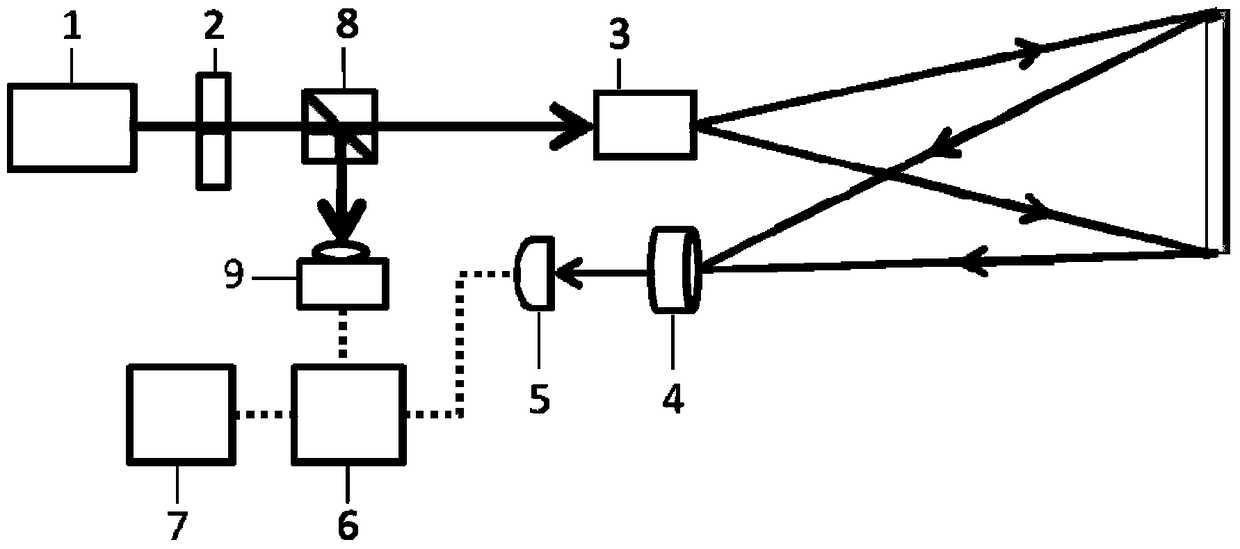
[0058] figure 2 It is a schematic structural diagram of a line scan imaging device according to a second preferred embodiment of the present invention. The difference from Embodiment 1 is that a laser beam splitting module 8 and a one-dimensional light intensity detection module 9 are added. The laser beam splitting module 8 is used to split the detection laser light, most of the laser light is used to illuminate the target area, and a small part of the laser light is received by the one-dimensional light intensity detection module 9 to obtain the one-dimensional distribution information of the light intensity modulation, and transmit it to The line-scan image reconstruction module 6; the line-scan image reconstruction module 6 calculates the laser intensity distribution of the detection laser corresponding to the narrow strip area at the target object from the one-dimensional distribution information of the light intensity.

[0059] The line laser source and intensity modul...

Embodiment 3

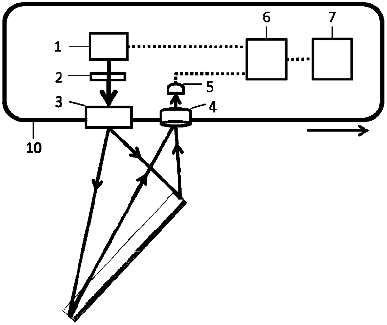
[0061] image 3 It is a schematic structural diagram of a line scan imaging device according to a third preferred embodiment of the present invention. Line laser source and intensity modulation module 1, beam space shaping module 2, emission module 3, echo collection module 4, light intensity point detection module 5, line scan image reconstruction module 6 and image stitching module 7 are installed on the motion platform 10 , moving together with the motion platform. The emission module 3 does not contain scanning elements. The scanning of the emitted laser beam is realized by the movement of the moving platform 10 , the bar-shaped beam scanning covers the entire imaging area, and the imaging results of each narrow strip-shaped area are spliced ​​to obtain the final imaging result. For each scan, the preset modulation information on the line laser source and the intensity modulation module 1 can be reused, thereby speeding up the modulation speed and reducing the storage sp...


PUM


Abstract

Disclosed in the invention is a line scanning imaging device. A line laser source and intensity modulation module (1) generates one-dimensional detection laser with random intensity distribution; a beam space shaping module (2) carries out space shaping on detection laser; a line scanning and emission module (3) carries out illumination on a target area by using long and narrow bar-shaped detection laser and line scanning is realized; a signal returned by a target is collected by an echo collection module (4); a light intensity point detection module (5) receives the signal; a line scanning image reconstruction module (6) carries out association calculation on the received point detection signal and light intensity distribution at the target position to realize reconstruction; and an image splicing module (7) carries out splicing of all bar-shaped imaging results to obtain an image of the target area. According to the invention, the linear array scanning illumination and point detection are combined, so that a long detection distance is obtained; and association calculation time is reduced based on one-dimensional image reconstruction. The method can be applied to scanning and imaging of a target during moving target imaging or rapid movement.

Description

technical field [0001] The invention relates to the technical field of optical imaging, and more particularly to a scanning imaging device based on a line detection light source and a point receiving detector that can image a long-distance and moving target. Background technique [0002] Traditional laser scanning imaging methods include point scanning and line scanning. The point scan method has low resolution and slow speed; the line scan method needs to use CCD or other array detectors as the receiving end, and the array detector has limited performance such as noise, response speed, and sensitivity, which limits the increase of imaging distance and imaging speed. . [0003] Generally speaking, point detection has higher noise control performance, response speed and higher sensitivity than linear array detection, but conventional point detection generally uses pixel-by-pixel detection and reconstruction of the target, so the laser repetition frequency Higher requirement...

Claims


Application Information

Patent Timeline
Patent Type & Authority Patents(China)
IPC IPC(8): G01S17/89
Inventor 杨晶赵巍许祖彦彭钦军张腾飞
Owner TECHNICAL INST OF PHYSICS & CHEMISTRY - CHINESE ACAD OF SCI
Why Eureka
Try Eureka