Double-frequency dipole antenna

A dipole antenna and dipole antenna technology, applied in the field of dual-frequency dipole printed antennas, can solve the problems of difficult adjustment of frequency band, complex antenna structure, difficult assembly, etc., and achieve the effects of wide range, improved competitiveness and reduced cost

Inactive Publication Date: 2016-10-05
ARCADYAN
View PDF5 Cites 0 Cited by
  • Summary
  • Abstract
  • Description
  • Claims
  • Application Information

AI Technical Summary

Problems solved by technology

[0005] In view of the above-mentioned problems in the prior art, one of the objects of the present invention is to provide a dual-frequency dipole antenna to solve

Method used


Image

  • Double-frequency dipole antenna
  • Double-frequency dipole antenna
  • Double-frequency dipole antenna

Examples


Example Embodiment

[0054] Hereinafter, embodiments of the dual-frequency dipole antenna according to the present invention will be described with reference to the relevant drawings. For clarity and convenience of the drawings, the components in the drawings may be exaggerated or reduced in size and proportion. To facilitate understanding, the same elements in the following embodiments are described with the same symbols.
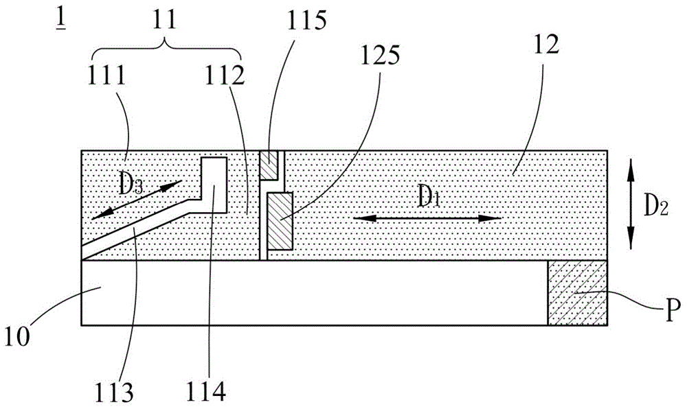
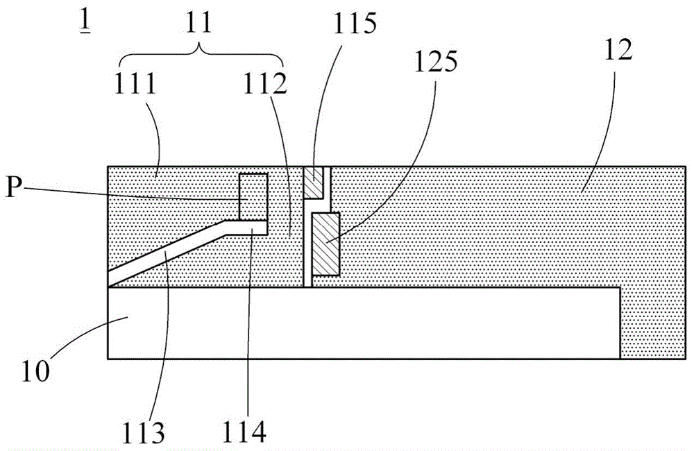
[0055] See figure 1 , Which is the first schematic diagram of the first embodiment of the dual-frequency dipole antenna of the present invention. This embodiment uses a printed antenna to realize the concept of the present invention. As shown in the figure, the dual-frequency dipole antenna 1 of this embodiment may include a substrate 10, a grounding area 12, a radiation body 11, a grounding point 125, and a feeding point 115.

[0056] The radiating body 11 is adjacent to the grounding area 12 and is disposed on the substrate 10. It may include a first radiator 111 and a second ra...


PUM


Abstract

The invention discloses a dual-frequency dipole antenna, which includes a substrate, a grounding area, a radiation body, a grounding point and a feeding point. The ground area can be disposed on the substrate. The radiating body can be adjacent to the grounding area, can be arranged on the substrate, and can include a first radiating body and a second radiating body, the first radiating body can be connected to the second radiating body, and the first radiating body and the second radiating body can There may be a groove between the bodies, and the size of the radiation body may be asymmetric to the size of the grounding area. The grounding point can be arranged on the substrate and can be connected to the grounding area. The feed-in point can be arranged on the substrate and can be connected to the radiation body, and the ground point and the feed-in point can be arranged adjacent to each other.

Description

technical field [0001] The invention relates to a dual-frequency dipole antenna, in particular to a dual-frequency dipole printed antenna with simple structure, low cost and easy adjustment of operating frequency band. Background technique [0002] With the advancement of science and technology, handheld electronic devices have become an indispensable equipment in people's lives. In order to cope with the massive use of handheld electronic In light and handy handheld electronic devices (such as mobile phones, notebook computers, etc.) or wireless transmission devices (such as wireless sharers, wireless network cards, etc.). For example, a planar inverted-F antenna (Planar Inverse-F Antenna, PIFA), monopole antenna (Monopole Antenna) or dipole antenna ( Dipole Antenna) has been widely used in various handheld electronic devices. [0003] However, prior art antennas suffer from a number of grievous disadvantages. For example, the bandwidth of the antenna in the prior art is...

Claims


Application Information

Patent Timeline
IPC IPC(8): H01Q1/38H01Q1/48
Inventor 杜健誌黄智勇罗国彰
Owner ARCADYAN
Why Eureka
Try Eureka