
Current sensing circuit and method for power converting device

A technology of current sensing and power conversion, which is applied in the direction of output power conversion devices, measuring current/voltage, measuring devices, etc., which can solve the problems of reducing system reliability and stability, failure to turn on in time, and abnormal current sensing circuit Operation and other issues to achieve the effect of improving reliability and stability

Active Publication Date: 2016-10-05
UPI SEMICON CORP
View PDF3 Cites 4 Cited by
  • Summary
  • Abstract
  • Description
  • Claims
  • Application Information

AI Technical Summary

Problems solved by technology

[0003] However, when the reverse current in the power conversion device is too large, the sensing switch in the existing current sensing circuit is often turned off, which causes the current sensing circuit to fail to operate normally.
Correspondingly, when the power conversion device stops generating reverse current, the existing current sensing circuit will not be able to turn on the sensing switch in time, so that the power conversion device cannot use the existing current sensing circuit to perform Feedback control, thereby reducing the reliability and stability of the system

Method used


Image

  • Current sensing circuit and method for power converting device
  • Current sensing circuit and method for power converting device
  • Current sensing circuit and method for power converting device

Examples


Embodiment Construction

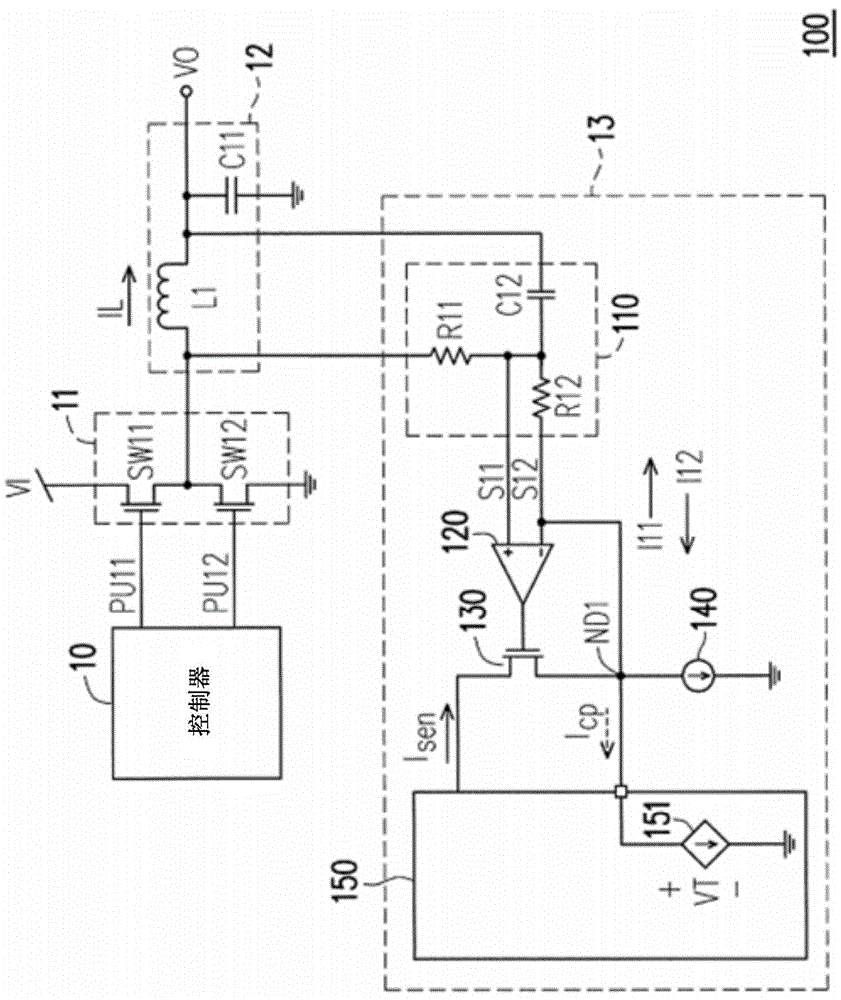
[0057] figure 1 It is a schematic diagram of a power conversion device according to an embodiment of the present invention. Such as figure 1 As shown, the power conversion device 100 includes a controller 10 , a switching circuit 11 , an impedance circuit 12 and a current sensing circuit 13 . Wherein, the controller 10 generates pulse signals PU11 and PU12 . The switching circuit 11 switches a plurality of transmission paths according to the pulse signals PU11 and PU12 to control the current flowing through the impedance circuit 12 . Thereby, the power conversion device 100 can convert the input voltage VI into the output voltage VO.

[0058] For example, the switching circuit 11 includes a switch SW11 and a switch SW12. also, figure 1 The embodiment takes the step-down impedance circuit 12 as an example, so the impedance circuit 12 includes an inductor L1 and a capacitor C11. Wherein, the switches SW11 and SW12 are connected in series to form the plurality of transmissi...


PUM


Abstract

A current sensing circuit and method for a power converting device are provided. The current sensing circuit includes a sensing unit, an amplifier, a sensing switch and a compensating circuit. The sensing unit detects an output current of the power converting device and provides a sensing signal. The amplifier has an output end and is coupled to the sensing unit to receive the sensing signal. The sensing switch is coupled to the output end of the amplifier. The compensating circuit is coupled to the sensing switch and a first input end of the amplifier. When the sensing signal is smaller than a threshold value, the compensating circuit activates a current compensation mechanism so as to maintain the sensing switch in a turned-on state.

Description

technical field [0001] The present invention relates to a current sensing circuit and method, and in particular to a current sensing circuit and method suitable for a power conversion device. Background technique [0002] Generally speaking, a power conversion device is provided with a current sensing circuit. In this way, the power conversion device can use the feedback signal generated by the current sensing circuit to perform feedback control, so as to improve the reliability and stability of the system. For example, when the load driven by the power conversion device is too small, the current sensing circuit can detect the reverse current (ie, negative current) in the power conversion device, thereby causing the power conversion device to switch to a different operation mode. [0003] However, when the reverse current in the power conversion device is too large, the sensing switch in the conventional current sensing circuit is often turned off, which causes the current ...

Claims


Application Information

Patent Timeline
IPC IPC(8): H02M3/156G01R19/165
Inventor 张志廉
Owner UPI SEMICON CORP
Learn More