Interferometric sensor

A technology of sensors and detectors, applied in the direction of converting sensor output, instruments, and using optical devices to transmit sensing components, etc., can solve problems such as not performing phase measurement

Inactive Publication Date: 2016-10-05
ABB POWER GRIDS SWITZERLAND AG
View PDF11 Cites 3 Cited by
  • Summary
  • Abstract
  • Description
  • Claims
  • Application Information

AI Technical Summary

Problems solved by technology

However, phase measurements are not performed in this technique, and contrast is required to be measured by scanning of multiple interfering fringes

Method used


Image

  • Interferometric sensor
  • Interferometric sensor
  • Interferometric sensor

Examples


Embodiment Construction

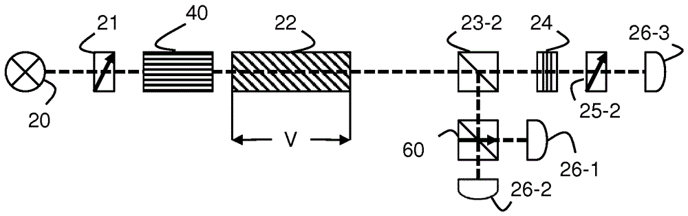
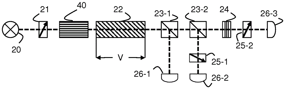
[0059] In the following, the example of an orthogonal polarization interferometer is used to describe the steps for signal manipulation or processing in the present invention. It should be noted that the basic principles of the described examples apply to many different types of interferometric sensors that otherwise suffer from period-wise ambiguities. Therefore, it can be applied to virtually any type of interferometer (Michelson, Mach-Zehnder, Fabry-Perot, Sagnac interferometer, etc.) with only minor differences in implementation or interpretation.

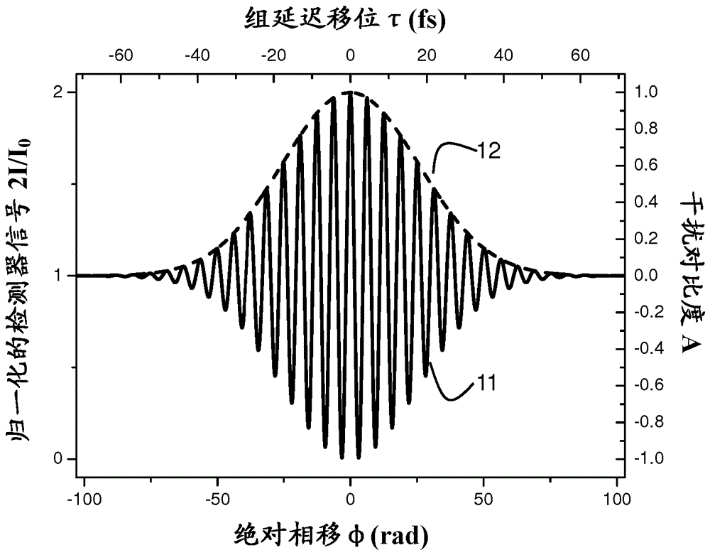
[0060] Typically, in an interferometer, the disturbed optical detector signal can be written as the sum of a fundamental term proportional to the output power of the light source and a sinusoidal term that varies as between phase shift of And change. In addition, the interference of non-monochromatic waves further introduces an additional modification of the temporal coherence of the waves to the detector signal . This ca...


PUM


Abstract

An interferometric sensor and related methods are provided, with a sensing element whereby a measurand induces a relative phase shift between two waves, at least one detector measuring an interference signal between the two waves, and further including a phase shift detection unit having as input the interference signal and determining a first measure representative of the principal value (PHI, 13) of the relative phase shift, and a contrast detection unit having as input the interference signal for determining a second measure (A, 12) representative of the cross-correlation between the two waves, and a further a processing unit for converting the first and second measures to a measurand value (x).

Description

technical field [0001] The invention relates to interferometric sensors such as electro-optical voltage sensors (especially for DC voltage) or fiber optic current sensors (FOCS), where the change in the parameter to be measured is related to the relative phase shift between two waves. Background technique [0002] Sensors that rely on the interference between two waves, usually two orthogonally polarized modes of waves, are known and used in a wide range of technical fields. The detector signals of these sensors are related to the cosine of the relative phase shift φ between the two waves. Therefore, phase shifts of φ and ±φ+2nπ (n is an integer, also referred to herein as a cycle counter) produce the same disturbance output and, therefore, cannot be distinguished from each other. Therefore, the unambiguous measurement range of the relative phase shift is limited to the range [0, π]. [0003] For example, bismuth germanate (Bi 4 Ge 3 o 12 , or BGO) crystals with their [...

Claims


Application Information

Patent Timeline
Patent Type & Authority Applications(China)
IPC IPC(8): G01D5/353G01D5/26G01R15/24G01B9/02
CPCG01D5/266G01D5/35306G01R15/241G01D5/353G01D5/35309
Inventor 顾逊S.V.马切泽K.博纳特A.弗兰克
Owner ABB POWER GRIDS SWITZERLAND AG
Why Eureka
Try Eureka