
Stator for rotary electric machine

A technology of rotating electrical machines and stators, applied in the field of stators of temperature sensors, can solve problems such as the reduction of the accuracy of coil temperature measurement

Active Publication Date: 2016-10-05
TOYOTA JIDOSHA KK
View PDF5 Cites 3 Cited by
  • Summary
  • Abstract
  • Description
  • Claims
  • Application Information

AI Technical Summary

Problems solved by technology

[0003] If a liquid cooling medium is supplied to the temperature sensor when the temperature of the coil is measured by the temperature sensor, the temperature sensor may measure the temperature of the liquid cooling medium instead of the temperature of the coil, so that the measurement accuracy of the coil temperature tends to decrease

Method used


Image

  • Stator for rotary electric machine
  • Stator for rotary electric machine
  • Stator for rotary electric machine

Examples


Embodiment Construction

[0021] Modes for carrying out the invention (hereinafter referred to as embodiments of the invention) will be described hereinafter with reference to the drawings.

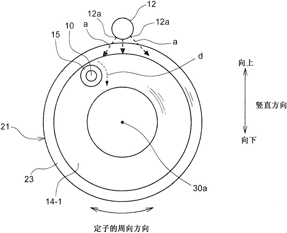
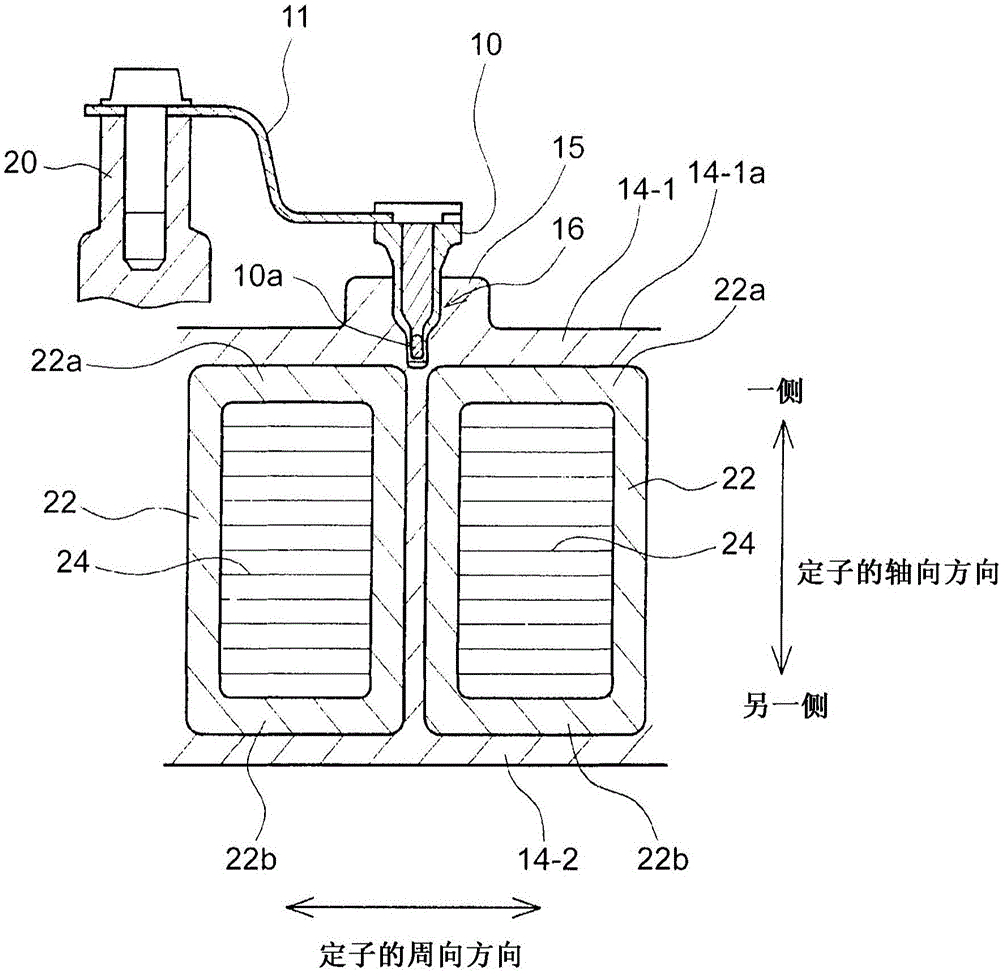
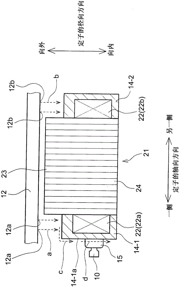
[0022] Figure 1 to Figure 4 Each drawing is a view showing a schematic configuration of a stator for a rotating electric machine according to the embodiment of the present invention. figure 1 A schematic structure viewed from the axial direction of the stator is shown. figure 2 A section along the circumferential direction of the stator is shown. image 3 A section as viewed from a direction perpendicular to the axial direction of the stator is shown. Figure 4 A configuration example of the stator core 21 and the coil 22 is shown. Figure 4 A part of the configuration of the stator core 21 and the coil 22 is shown with respect to the circumferential direction of the stator, but the configuration of the remaining part (not shown) is the same as that shown in the drawings in terms of configuration.

[0023] T...


PUM


Abstract

A cooling oil is supplied from a cooling pipe (12) to an outer peripheral surface of a mold resin (14-1), and a thermistor (10) for measuring a temperature of a coil (22) is provided at one end portion of the mold resin (14-1) in an axial direction of a stator. A bulge portion (15) for restraining the cooling oil from being supplied to the thermistor (10) is provided bulging outward in the axial direction of the stator in such a manner as to surround at least part of a periphery of the thermistor (10), at one end portion of the mold resin (14-1) in the axial direction of the stator.

Description

technical field [0001] The present invention relates to a stator for a rotating electrical machine, and more particularly to a stator provided with a temperature sensor for measuring the temperature of a coil. Background technique [0002] In the stator for rotating electrical machines disclosed in Japanese Patent Application Laid-Open No. 2010-141968 (JP-2010-141968 A), in order to measure the temperature of the coil, a thermistor (temperature sensor) is removed from the resin molded coil end The position on the outer peripheral surface is inserted and fixed. In order to suppress the cooling oil (liquid cooling medium) supplied to the outer peripheral surface of the molded resin from falling on the thermistor, the terminal block of the rotating electric machine mounted on the outer peripheral surface of the coil end is provided with an oil inflow suppressing member so as to cover thermistor. [0003] If a liquid cooling medium is supplied to the temperature sensor when th...

Claims


Application Information

Patent Timeline
Patent Type & Authority Applications(China)
IPC IPC(8): H02K11/25H02K1/20
CPCH02K1/20H02K9/19H02K15/12H02K11/25H02K1/146H02K3/18H02K9/24
Inventor 松本隆志
Owner TOYOTA JIDOSHA KK
Learn More