
Self-rotating automatic material receiver

A material catcher and automatic technology, which is applied in metal processing and other directions, can solve the problems of easy flying of the workpiece, unsoft movements, and large swing range, etc., and achieve the effect of small swing range, soft motion, and small space occupation

Inactive Publication Date: 2016-10-12
SHANDONG LUNAN MACHINE TOOL
View PDF8 Cites 3 Cited by
  • Summary
  • Abstract
  • Description
  • Claims
  • Application Information

AI Technical Summary

Problems solved by technology

The currently used automatic material catcher bed generally has defects such as large swing range, soft movement, and easy flying of workpieces.

Method used


Image

  • Self-rotating automatic material receiver
  • Self-rotating automatic material receiver
  • Self-rotating automatic material receiver

Examples


Embodiment

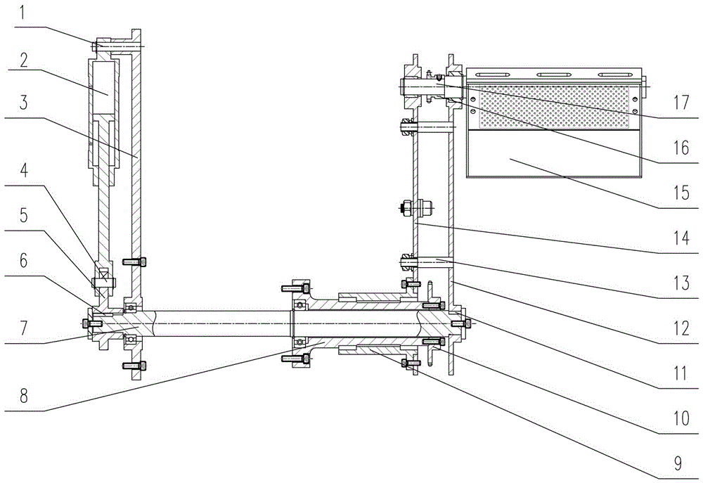
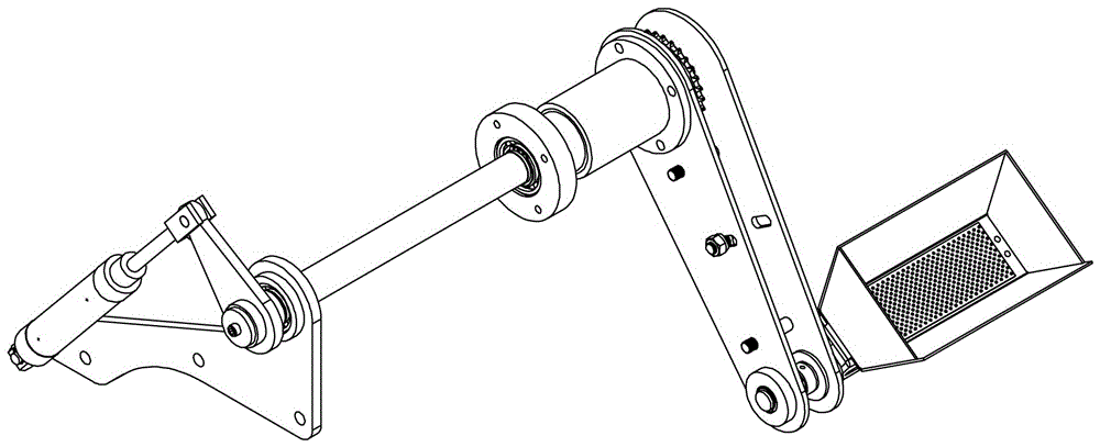
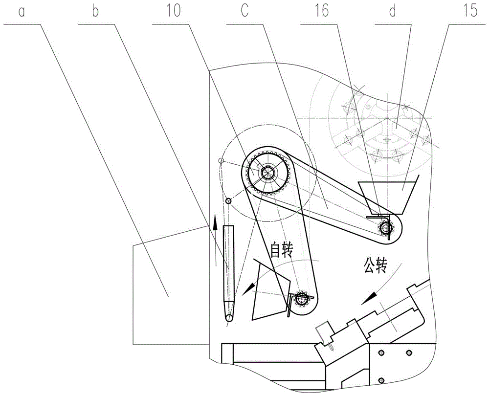
[0027] Such as figure 1 As shown, the support plate 3 and the support sleeve 8 are installed on the side of the bedside box by bolts, and the support plate 3 is equipped with pin shaft I and transmission shaft 7. The base of the rod cylinder 2 rotates on the pin shaft I, and the other end of the rod cylinder 2 is hinged on the driving arm 5 of the transmission shaft 7 . The rod cylinder 2 and the driving arm 5 are connected through the pin shaft 4, and the driving arm 5 and the transmission shaft 7 are connected through the flat key 6. Through the above connection, the reciprocating linear motion of the rod cylinder 2 drives the driving arm 5 into the positive direction of the transmission shaft 7. Anti-rotational movement.

[0028] Wherein, the large sprocket 10 is fixedly installed on the supporting sleeve 8 and is a non-moving part. The swing arm is formed by connecting the front plate 12 and the rear plate 14 through the pin shaft III. The front plate 12 is connected wi...


PUM


Abstract

The invention discloses a self-rotating automatic material receiver. The invention aims to provide the self-rotating automatic material receiver which is small in amplitude of swing and flexible in movement, and is particularly suitable for an automatic feeding numerically controlled lathe. In order to realize the purpose, the invention adopts the technical scheme that the material receiver mainly comprises a supporting unit, a driving unit and a movement executing unit, wherein the supporting unit is mounted on the side face of a headstock, the driving unit is mounted on the supporting unit, and the driving unit is connected to the movement executing unit; the driving unit comprises a driving element and a transmission shaft driven by the driving element; the movement executing unit comprises a swing arm, a transmission mechanism mounted on the swing arm and a material receiving box, the swing arm is mounted at one end of the transmission shaft, the swing arm is movably connected to a supporting sleeve, and a rotary shaft of the material receiving box is connected to the supporting sleeve through the transmission mechanism. The self-rotating automatic material receiver disclosed by the invention integrates revolution of the swing arm and self-rotation of a magazine and is small in amplitude of swing, flexible in movement, flexible and reliable in movement and small in occupied space.

Description

technical field [0001] The invention relates to a loading and unloading device for a machine tool, in particular to a self-type automatic material receiver. Background technique [0002] Automatic loading and unloading devices are an important part of high-productivity machinery or automated machine tools. When the machine tool realizes the automation of the processing cycle, it is only a semi-automatic machine tool. Only when the semi-automatic machine tool is equipped with an automatic loading and unloading device designed according to the characteristics of the workpiece to realize automatic loading and unloading, can it become an automatic machine tool or realize process automation. The automatic feeder can be installed on various types of automatic lathes, so that the lathe workpiece and cutting slag can be completely separated. Manual cleaning is no longer required. The currently used automatic feeder beds generally have defects such as large swing range, unsoft move...

Claims


Application Information

Patent Timeline
IPC IPC(8): B23B15/00
CPCB23Q7/00B23Q7/03
Inventor 刘斌王婷婷李天昊刘春联吕刚徐岩
Owner SHANDONG LUNAN MACHINE TOOL
Learn More