Welding method of LED wick

A technology of LED wicks and welding methods, applied in welding equipment, welding/welding/cutting items, auxiliary devices, etc., can solve the problems of high production costs and low work efficiency, reduce production costs, improve work efficiency, and reduce personnel cost effect

Inactive Publication Date: 2016-10-12
镇江晨光焊接设备制造有限公司
View PDF0 Cites 3 Cited by
  • Summary
  • Abstract
  • Description
  • Claims
  • Application Information

AI Technical Summary

Problems solved by technology

[0003] However, there are currently a variety of spiral (also called cross) LED wicks, and the LED light strips are welded between short-leg guide wires and long-leg guide wires that do not correspond to each other, such as figure 1 Shown is a spiral LED wick 100. When welding this kind of LED wick, because the LED light bar 130 needs to be welded between the short-leg guide wire 120 and the long-leg guide wire 110 that are staggered from each other, the commonly used automatic horizontal welding device The welding process cannot be completed, and the welding process needs to be manually completed, with low work efficiency and high production costs.

Method used


Image

  • Welding method of LED wick
  • Welding method of LED wick
  • Welding method of LED wick

Examples


Embodiment Construction

[0024] The preferred embodiments of the present invention will be described in detail below in conjunction with the accompanying drawings, so that the advantages and features of the present invention can be more easily understood by those skilled in the art, so as to define the protection scope of the present invention more clearly.

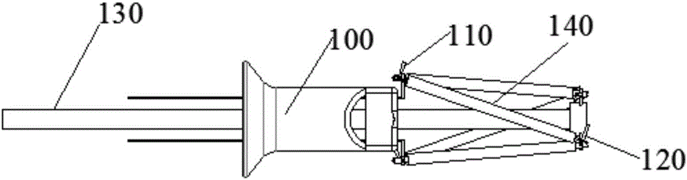
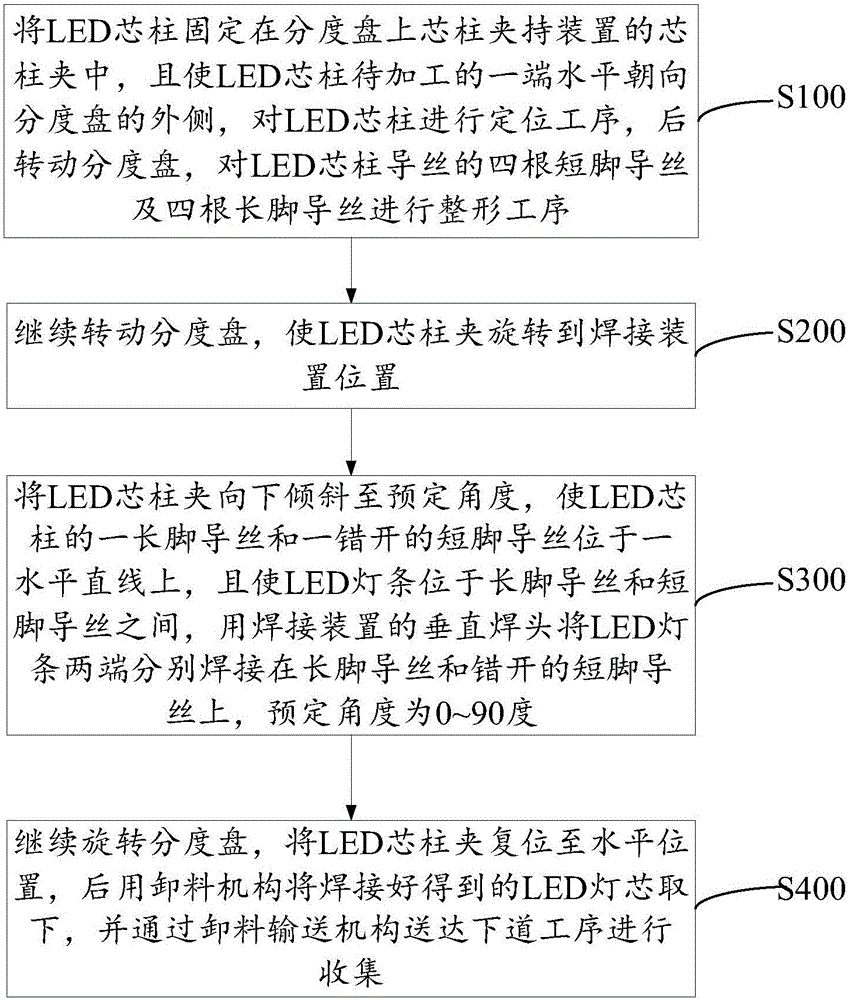
[0025] see Figure 1 to Figure 8 , a LED wick welding method, comprising the following steps:

[0026] Step S100, fix the LED stem in the stem clamp of the stem clamping device on the indexing plate, and make the end of the LED stem to be processed horizontally face the outside of the indexing plate, perform the positioning process on the LED stem, and then Turn the indexing plate to carry out the shaping process on the four short-leg guide wires and the four long-leg guide wires of the LED stem guide wires.

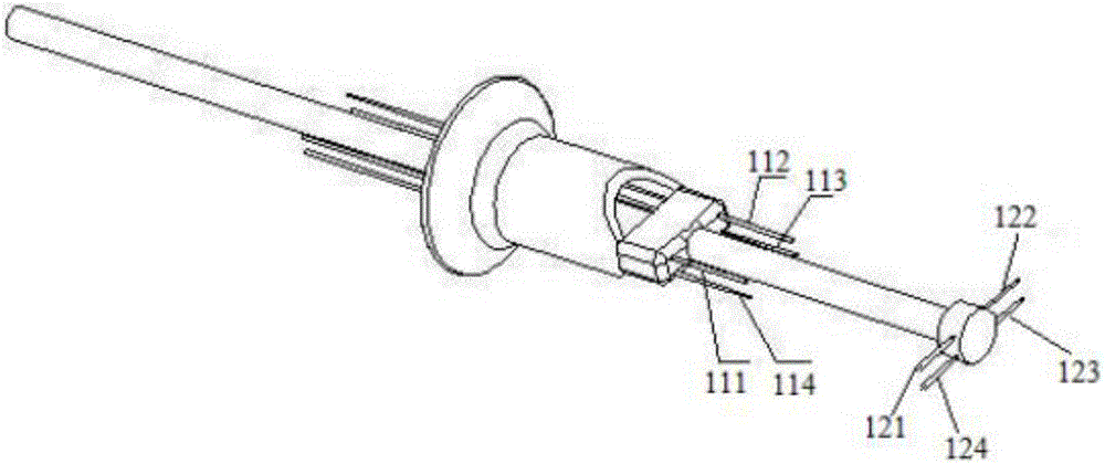
[0027] Wherein, the structure of the LED stem 100 before shaping is as follows: image 3 shown. The shaping process also includes: the ...


PUM


Abstract

The invention provides an LED wick welding method. The LED wick welding method includes the following steps: fixing the LED stem in the stem clip of the stem clamping device, performing a shaping process on the four short-leg guide wires and the four long-leg guide wires of the LED stem; The LED stem clip is inclined downward to a predetermined angle, so that a long-leg guide wire and a staggered short-leg guide wire of the LED stem are located on a horizontal straight line, and the LED light bar is positioned between the long-leg guide wire and the short-leg guide wire. Between; reset the LED stem clamp to the horizontal position, and then use the unloading mechanism to remove the welded LED wick. In the above-mentioned LED wick welding method, since the stem clamping device is tilted during the welding process so that the long-leg guide wire and the staggered short-leg guide wire are located on the same horizontal plane, the welding process for the spiral LED wick is realized, and the automatic welding operation is realized. The working efficiency is greatly improved, and the production cost of the whole LED wick is reduced.

Description

technical field [0001] The invention relates to the field of LED wicks, in particular to an LED wick welding method. Background technique [0002] LED filament lamps are a new variety of LED lamps that have emerged in recent years. Because of their advantages in energy saving, environmental protection, and long life, as well as the comprehensive advantages of traditional incandescent lamps, they are very popular among consumers and have a good market prospect. At present, the commonly used LED wick welding process is to weld the LED light bar between the upper and lower corresponding short and long guide wires respectively. [0003] However, there are currently a variety of spiral (also called cross) LED wicks, and the LED light strips are welded between short-leg guide wires and long-leg guide wires that do not correspond to each other, such as figure 1 Shown is a spiral LED wick 100. When welding this kind of LED wick, because the LED light bar 130 needs to be welded betw...

Claims


Application Information

Patent Timeline
Patent Type & Authority Applications(China)
IPC IPC(8): B23K3/00B23K3/08B23K101/36
CPCB23K3/00B23K3/08B23K3/087B23K2101/36
Inventor 张小强
Owner 镇江晨光焊接设备制造有限公司
Why Eureka
Try Eureka