
Plastic smelting device

A plastic and rotor technology, applied in metal processing and other directions, can solve the problems of plastic pipe damage, cutter damage, uneven force on plastic pipes, and achieve the effect of preventing damage and uniform force.

Pending Publication Date: 2016-10-12
重庆敏驰塑胶有限公司
View PDF0 Cites 3 Cited by
  • Summary
  • Abstract
  • Description
  • Claims
  • Application Information

AI Technical Summary

Problems solved by technology

Existing plastic pipe cutting devices usually only have one cutter, so when the cutter rotates, periodically changing pressure will be formed on the outer surface of the plastic pipe, resulting in uneven stress on the plastic pipe and easy damage to the plastic pipe; After the tube is cut, it will fall directly, and it is often damaged by the high-speed rotating cutter

Method used


Image

  • Plastic smelting device
  • Plastic smelting device

Examples


Embodiment Construction

[0018] The present invention will be described in further detail below by means of specific embodiments:

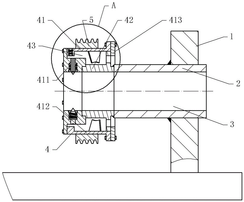
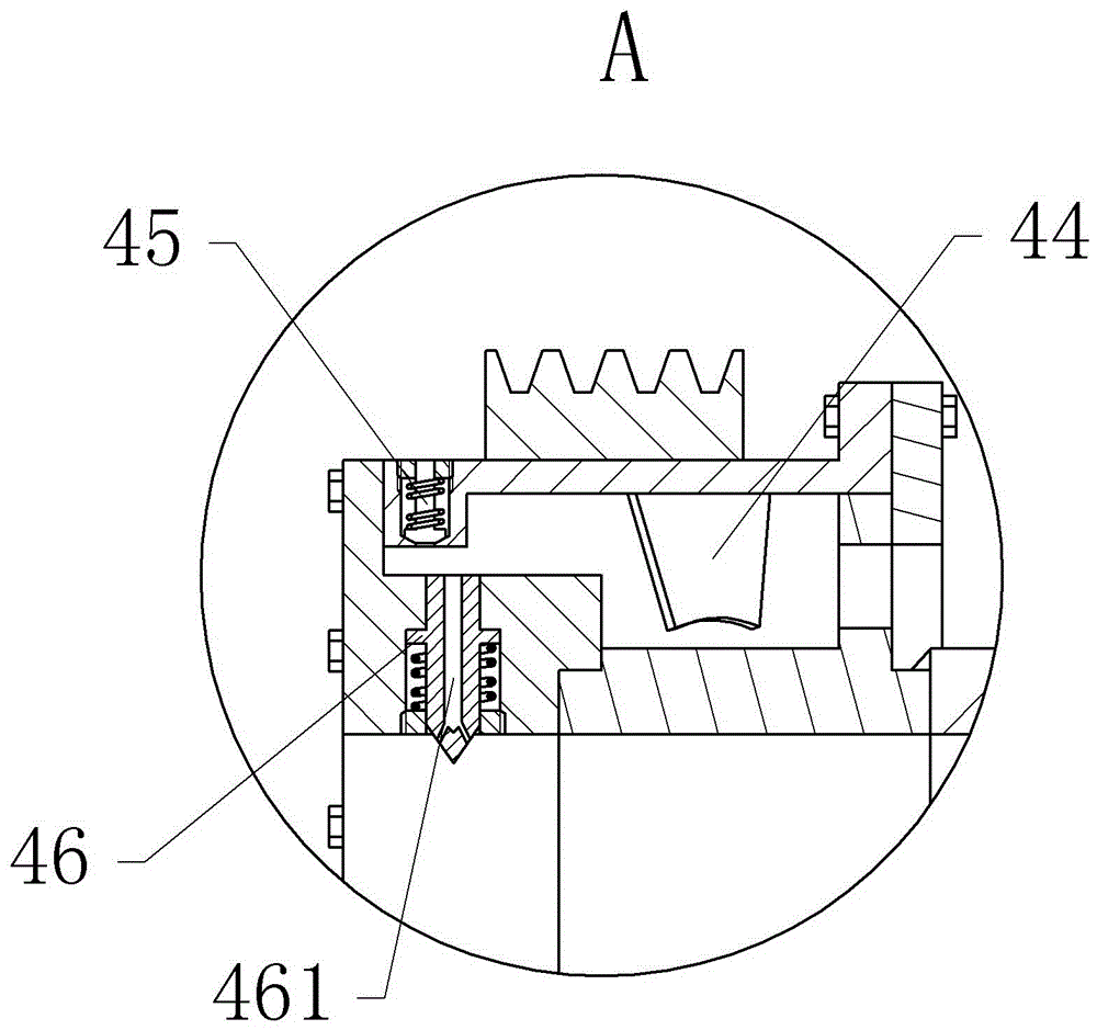
[0019] The reference signs in the drawings of the description include: frame 1, cantilever 2, central through hole 3, cutting mechanism 4, pulley 5, rotor 41, stator 42, pressure chamber 43, rotary vane 44, pressure regulating valve 45, cutter 46. ​​Left end cap 411 , outer casing 412 , right end cap 413 , vent hole 461 .

[0020] The embodiment is basically as figure 1 , figure 2 Shown:

[0021] The plastic smelting device of this embodiment includes a frame 1 and a driving motor; a cantilever 2 is fixed on the frame 1 , one end of the cantilever 2 is fixed on the frame 1 , and a cutting mechanism 4 is provided at the other end of the cantilever 2 . The cutting mechanism 4 includes a stator 42 and a rotor 41, the stator 42 is welded on the cantilever 2, the rotor 41 is connected to the stator 42 in rotation, an air suction chamber is arranged between the stator 42 an...


PUM


Abstract

The invention discloses a plastic smelting device and relates to the field of plastic machining. The plastic smelting device comprises a rack and a driving motor. A cantilever is fixed on the rack. One end of the cantilever is fixed on the rack and the other end of the cantilever is provided with a cutting mechanism. The cutting mechanism comprises a stator which is fixed on the cantilever and a rotor which is rotationally connected with the stator. A center through hole interpenetrates the centers of the rotor, the stator and the cantilever. An air suction cavity is arranged between the stator and the rotor. A rotary vane rotating with the rotor is arranged in the air suction cavity and the air suction cavity is divided into a pressure chamber and an air inlet passage by the rotary vane. The air inlet passage communicates with the outside. A plurality of cutters which are uniformly distributed along the center of the rotor are arranged on the rotor and the cutters can slide radially along the rotor. Tensioning springs sleeves outside the cutters. The rotor can be driven to rotate by the driving motor. According to the plastic smelting device, a plastic pipe can be uniformly forced when cut and located in the center through hole after cut, so that damage of the plastic pipe can be prevented.

Description

technical field [0001] The invention relates to the field of plastic processing, in particular to a plastic melting device. Background technique [0002] Plastic pipe is a kind of non-metallic pipe. Its good performance has been widely recognized by all walks of life in the world. Compared with ordinary plastic, it has no toxic and side effects. Its mechanical properties, thermal stability, water resistance, alkali resistance, acid resistance and other properties are greatly improved. It can be widely used in chemical industry, aerospace, military, family, hospital and other fields, and has good promotion value and social benefits. [0003] In the melting process of plastic pipes, cutting to length is an important process, which directly determines whether two sections of plastic pipes can be smelted together; the existing plastic pipe cutting devices mostly use cutting plastic pipes from the outside of the plastic pipe; the cutting method is usually There are two types, on...

Claims


Application Information

Patent Timeline
IPC IPC(8): B26D1/29B26D5/04B26D7/26
CPCB26D1/29B26D5/04B26D7/2614B26D7/2628
Inventor 杨治焱
Owner 重庆敏驰塑胶有限公司
Learn More