
Multifunctional power recovery vehicle

An electric emergency repair vehicle, multi-functional technology, applied in the direction of motor vehicles, vehicle parts, goods transport vehicles, etc., can solve the problems affecting the efficiency and effect of emergency repair and rescue, inconvenient use and maintenance, and poor locking security, etc. The effect of service level, improved power supply reliability, good locking security

Inactive Publication Date: 2016-10-12
福建国睿智能电网技术有限公司
View PDF9 Cites 3 Cited by
  • Summary
  • Abstract
  • Description
  • Claims
  • Application Information

AI Technical Summary

Problems solved by technology

[0005] The purpose of the present invention is to provide a multi-functional electric emergency repair vehicle, which can solve the obstacles existing in the prior art when it is raised, the structure is complex and bulky, the use and maintenance are very inconvenient, time-consuming and laborious, and affect the efficiency of emergency repair and rescue. And effect, poor locking security, cumbersome operation and other issues

Method used


Image

  • Multifunctional power recovery vehicle
  • Multifunctional power recovery vehicle
  • Multifunctional power recovery vehicle

Examples


Embodiment 1

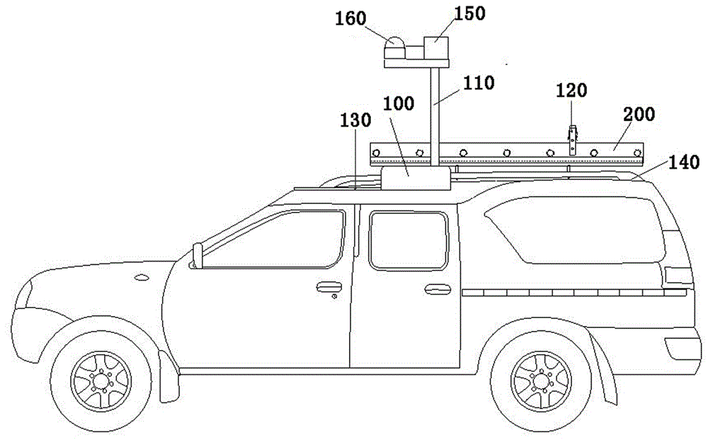
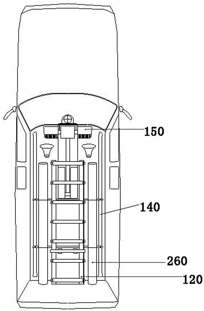
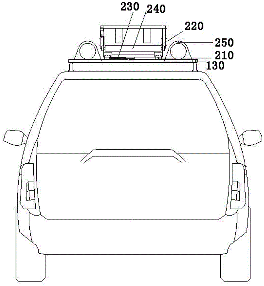
[0048] An electric emergency repair vehicle with a track insulation ladder fixing frame, such as Figure 1 to Figure 4As shown, it includes a curved arm type bracket arranged on the vehicle body, and the curved arm type bracket includes a transverse base 100 and a longitudinal support 110 that is rotatably connected with the transverse base 100; The insulating ladder fixing frame 120 is provided with a sliding track 200, and the sliding track 200 is connected with the longitudinal bracket 110 of the crank arm type support; the sliding track 200 is arranged on the fixing frame base 210, and the rear part of the fixing frame base 210 is provided with The buckle device 220 is provided with a latch 230 matching with the buckle device 220 at the rear end of the base 210 of the fixing frame.

[0049] In the above embodiment, the rear end of the fixing frame base 210 is provided with a fixing frame limiting device 240 .

[0050] In the above embodiment, the bottom supporting frame 1...

Embodiment 2

[0074] A kind of emergency repair vehicle with a power-assisted roller insulation ladder fixing frame, such as Figure 5 to Figure 7 As shown, it includes a curved arm type bracket arranged on the vehicle body, and the curved arm type bracket includes a transverse base 100 and a longitudinal support 110 that is rotatably connected with the transverse base 100; connected, the insulating ladder fixed frame 120 is provided with a roller 270, the roller 270 is arranged on the fixed frame base 210, the rear part of the fixed frame base 210 is provided with a buckle device 220, and the rear end of the fixed frame base 210 is provided with a The latch 230 matches the buckle arrangement.

[0075] In the above embodiment, the rear end of the fixing frame base 210 is provided with an insulating ladder anti-slip device 280 .

[0076] In the above embodiments, the insulating ladder anti-slip device 280 includes a fixing frame limiting component 281 .

[0077] In the above embodiments, t...

Embodiment 3

[0101] A recovery vehicle with a quick lock toolbox, such as Figure 8 with Figure 9 As shown, it includes a toolbox 300 arranged on the vehicle body. The periphery of the toolbox 300 is provided with a frame body, and the outer end surface of the toolbox 300 is provided with a lock body. A shaft hole is provided at the upper relative position, and a rotating shaft is inserted into the shaft hole. A handle 320 is connected to the rotating shaft, and a spring buckle is connected to the inner side of the handle 320. card slot.

[0102] In the above embodiments, the tool box 300 is provided at a position inside the trunk on the vehicle body.

[0103] In the above embodiments, the toolbox 300 is configured as a drawer structure that can be pulled back and forth, or a drag structure that can be pushed and pulled left and right.

[0104] In the above embodiments, the handle 320 is configured as a flip switch.

[0105] In the above embodiments, the handle 320 is provided with a pu...


PUM


Abstract

The invention provides a multifunctional power recovery vehicle. The multifunctional power recovery vehicle comprises a crank arm type bracket, a toolkit and a baggage carrier, which are arranged on a vehicle body, wherein the crank arm type bracket comprises a transverse base and a longitudinal support which is in rotary connection with the transverse base; a frame body is arranged at the periphery of the toolkit; the multifunctional power recovery vehicle further comprises an insulating ladder fixing frame with a special part and a lock body which is arranged on the end face of the outer side of the toolkit; the crank arm type bracket is connected with the insulating ladder fixing frame with the special part; the lock body comprises an outer frame; shaft holes are formed in relative positions at two side edges of the outer frame; a rotary shaft stretches into the shaft holes; the rotary shaft is connected and provided with a handle; the inner side of the handle is connected and provided with a spring buckle; a clamping groove is formed in the position, corresponding to the spring buckle, on the frame body. Furthermore, the power supply reliability and a high-quality service level of a distribution network are improved; doing rush repairs at night , getting assistance from a recovery commanding center and climbing to repair in high can be effectively realized; crank arm illumination and monitoring equipment can be automatically hoisted without obstacles; the multifunctional power recovery vehicle has the advantages of good locking safety, simple and easy operation, time saving and labor saving, safety and high efficiency.

Description

technical field [0001] The invention belongs to the technical field of electric power emergency repair, and in particular relates to a multifunctional electric electric emergency repair vehicle. Background technique [0002] At present, in the power system, with the rapid growth of the communication scale, the power emergency repair work is becoming more and more important. All electric power supply companies are equipped with emergency repair vehicles; Most vehicles adopt a structure in which lighting, monitoring equipment and aerial ladders are placed on the top of the emergency repair vehicle. However, most of the existing electric emergency repair vehicles have the problem of obstacles when the lighting and monitoring equipment are raised, which affects the efficiency and effect of emergency repair and rescue. In order to standardize the placement of emergency repair tools, most of them set up tool material boxes for different tools in the rear compartment of the emergen...

Claims


Application Information

Patent Timeline
Patent Type & Authority Applications(China)
IPC IPC(8): B60P3/00B60R9/04B60R3/00B60R11/06
CPCB60P3/00B60R3/00B60R9/04B60R11/06
Inventor 赖必贵赖兴华赖元发
Owner 福建国睿智能电网技术有限公司
Learn More