Filter Circuit, Differential Transmission System Having Same, and Power Supply

a filter circuit and differential transmission technology, applied in the field of differential transmission systems, can solve the problems of common mode chokes, /b> may lose the effect of suppressing common mode noise, and it is difficult for filter circuits to further improve the effect of suppressing emi radiation, etc., to achieve greater suppression of emi radiation, increase the speed of serial transmission, and improve the quality of serial signals

Inactive Publication Date: 2007-11-01
PANASONIC CORP
View PDF5 Cites 46 Cited by
  • Summary
  • Abstract
  • Description
  • Claims
  • Application Information

AI Technical Summary

Benefits of technology

[0013] Further increases in the speed of serial transmission requires a higher quality of serial signals and greater suppression of EMI radiation to the surroundings, by more effectively suppressing the occurrences of common mode noises in differential lines. On the other hand, further improvements in reliability of power supply require a higher quality of converted electric power and greater suppression of EMI radiation to the surroundings, by more effectively suppressing the occurrences of common mode noises in power lines. Thus, in either of the differential transmission systems and power supplies, it is desirable to further improve filter circuits having an effect of suppressing common mode noises.

Problems solved by technology

In other words, this filter circuit is difficult to further improve the effect thereof of suppressing EMI radiation.
Furthermore, when common mode currents become excessive, the core of the common mode choke 110 is magnetized to saturation, and then the common mode choke 110 may lose the effect of suppressing common mode noises.
In other words, in this filter circuit, it is difficult to further improve the effect of suppressing common mode noises while maintaining the compact core of the common mode choke 110.

Method used


Image

  • Filter Circuit, Differential Transmission System Having Same, and Power Supply
  • Filter Circuit, Differential Transmission System Having Same, and Power Supply
  • Filter Circuit, Differential Transmission System Having Same, and Power Supply

Examples


embodiment 1

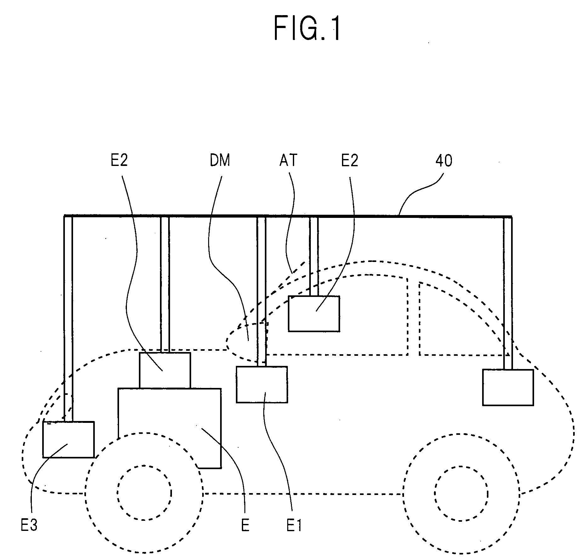
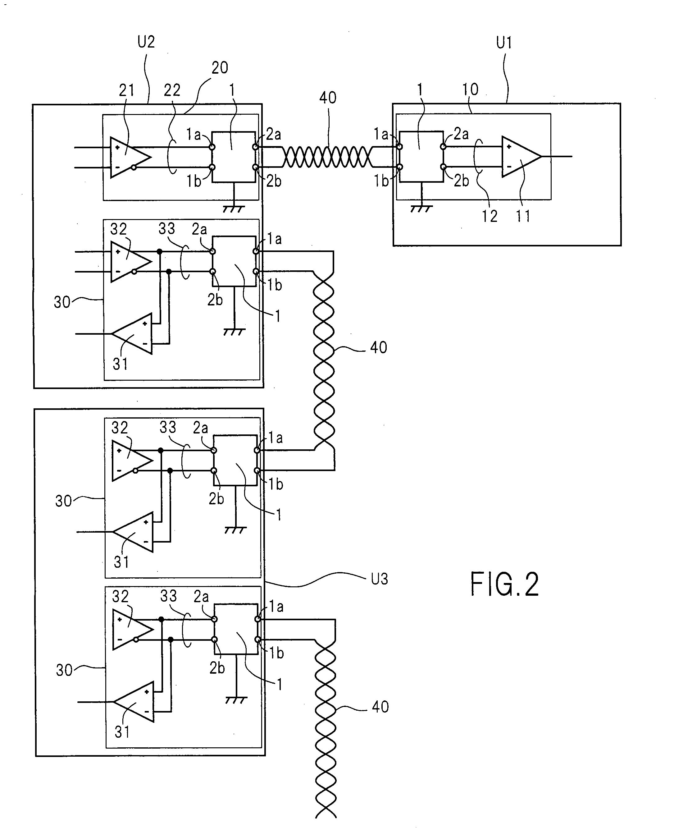
[0108] A differential transmission system according to Embodiment 1 of the present invention is preferably installed in an in-car LAN such as CAN. (cf. FIG. 1). Various ECUs connected to the in-car LAN include, for example; ECUs E1 to control a driving system (powertrain) such as an engine, a transmission, and a brake; ECUs E2 to control safety devices (safety system) such as an ABS and airbags; and ECUs E3 to control attachments (body control system) such as headlights, an air conditioner, and side-view mirrors. In-car-LAN-connected devices further include; various sensors such as an in-car camera, a laser for measurement of a distance between cars, and an acceleration sensor; information electronic appliances (ITS) E4 such as a car navigation system and an ETC; and AV apparatuses such as a DVD player and a stereo system component. Such ECUs and in-car electronic appliances (hereinafter, abbreviated as ECUs, etc.) are preferably connected in bus configuration, or alternatively, may...

embodiment 2

[0128] A differential transmission system according to Embodiment 2 of the present invention is preferably installed into an in-car LAN, like the system according to Embodiment 1. Embodiment 2 of the present invention differs from Embodiment 1 in the way that a filter circuit 1 includes a multilayer inductor or a thin film inductor. A description of components according to Embodiment 2 of the present invention that are similar to components according to Embodiment 1, can be found above in the description of Embodiment 1.

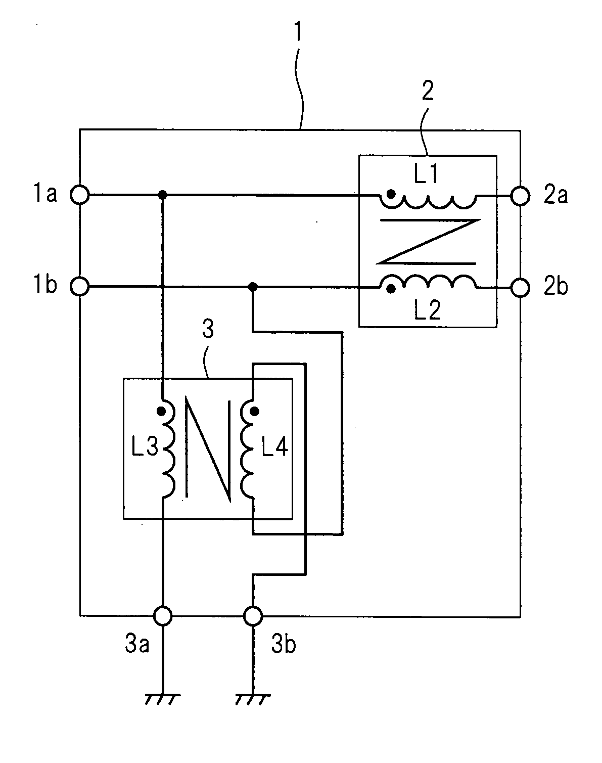
[0129] The filter circuit 1 according to Embodiment 2 of the present invention is expressed by an equivalent circuit similar to that of the filter circuit according to Embodiment 1 (cf. FIG. 14). However, all inductors L1, L2, L3, and L4, which are included in a common mode choke 2 and a normal mode choke 3, are multilayer inductors or thin film inductors, and they are integrated in the same chip 2B (cf. FIGS. 15, 16, and 17), in contrast to the filter circuit accor...

embodiment 3

[0149] A differential transmission system according to Embodiment 3 of the present invention is preferably installed into an in-car LAN, like the system according to Embodiment 1. Embodiment 3 of the present invention differs from Embodiments 1, 2 in the way that a filter circuit 1 includes a terminator element. A description of components according to Embodiment 3 of the present invention that are similar to components according to Embodiment 1 or 2, can be found above in the description of Embodiment 1 or 2.

[0150] The filter circuit 1 according to Embodiment 3 of the present invention is expressed by an equivalent circuit similar to that of the filter circuit 1 according to Embodiment 1 (cf. FIGS. 27, 28, 29, 30, 31). However, terminator elements Z1 and Z2 are connected to a normal mode choke 3, in contrast to the filter circuit 1 according to Embodiment 1. The terminator elements Z1 and Z2 are impedance elements, preferably capacitors, or alternatively, may be inductors, varisto...


PUM


Abstract

In a filter circuit (1), a common mode choke (2) and a normal mode choke (3) have extremely high and low impedances, respectively, for common mode signals received through two input terminals (1a and 1b). The chokes have the opposite impedance characteristics for differential signals. In particular, the difference in impedance is large. Furthermore, the normal mode choke (3) is installed as a previous stage of the common mode choke (2). Accordingly, common mode noises which enter the two input terminals (1a and 1b) penetrate the normal mode choke (3), but neither penetrate the common mode choke (2) nor are reflected from the common mode choke (2). In particular, common mode currents flow through the normal mode choke (3) but do not flow through the common mode choke (2).

Description

TECHNICAL FIELD [0001] The present invention relates to a differential transmission system that allows communications between electronic appliances using a differential transmission scheme, and a power supply that converts electric power supplied by an external power supply such as a commercial AC power supply, and in particular relates to filter circuits that are installed in the system and the power supply. BACKGROUND OF THE INVENTION [0002] Processing speeds of general electronic appliances have been still increasing in order to satisfy demand for multifunctionality and higher performance. This requires further increases in the speed of communications between electronic appliances. Serial transmission has advantages over parallel transmission in the further increases in the speed of communications. Accordingly, serial transmission schemes are widely adopted by various standards, such as USB, EEEE 1394, LVDS, DVI, HDMI, serial ATA, PCI express, in recent years. In particular, the ...

Claims


Application Information

Patent Timeline
Patent Type & Authority Applications(United States)
IPC IPC(8): H03H7/38
CPCH01F17/0013H01F2017/0093H03H7/09H03H2001/0085H03H7/427H04L12/40032H04L2012/40215H04L2012/4026H04B3/30
Inventor SUENAGA, HIROSHISHIBATA, OSAMUSAITO, YOSHIYUKIKATTA, NOBORUMIZUGUCHI, YUJI
Owner PANASONIC CORP
Why Eureka
Try Eureka