Braking method of a vehicle booster braking device

A braking device and vehicle technology, applied in the direction of braking transmission, brakes, vehicle components, etc., can solve the problems of affecting braking performance, unable to generate pressure oil, unable to realize power-assisted braking, etc., and achieve the effect of preventing traffic accidents

Active Publication Date: 2018-06-29
JIANGSU HENGLI BRAKE MFG
View PDF7 Cites 0 Cited by
  • Summary
  • Abstract
  • Description
  • Claims
  • Application Information

AI Technical Summary

Problems solved by technology

[0002] As people pay more and more attention to the protection of the natural environment, pollution-free electric vehicles have become a popular direction. Due to the cancellation of the traditional fuel engine, the original vacuum booster loses vacuum and cannot assist braking.
Chinese Patent Application No. 200810163260.5 discloses a hydraulic power-assisted braking device, which uses a hydraulic booster instead of a vacuum booster to solve the problem that the power-assisted braking cannot be performed due to the cancellation of the fuel engine, but the above-mentioned invention is driven by the engine. After the engine is turned off, the hydraulic pump will no longer work, so it will not be able to produce pressure oil, so when the engine is turned off, the power-assisted braking cannot be realized, which will cause traffic accidents
The above invention uses hydraulic oil for braking. Since the maximum flow rate of hydraulic oil generally does not exceed 6m / s, when the brake pedal assembly is far away from the brake, the pressure oil acts on the braking force of the brake when the brake pedal assembly is stepped on. The slave cylinder takes a long time, so there will be braking hysteresis, and because the general front wheel brake is closer to the brake pedal assembly, the pressure oil will first enter the brake cylinder of the front wheel brake for braking, and the front wheel brake and When the distance between the rear wheel brakes is relatively long, the time difference between the pressure oil acting on the brake cylinders on the front wheel brakes and the rear wheel brakes is relatively long, and the rear wheel brakes will obviously lag behind, seriously affecting the braking performance and causing traffic accidents. ACCIDENT

Method used


Image

  • Braking method of a vehicle booster braking device

Examples


Embodiment Construction

[0018] Below in conjunction with accompanying drawing and given embodiment, the present invention will be further described:

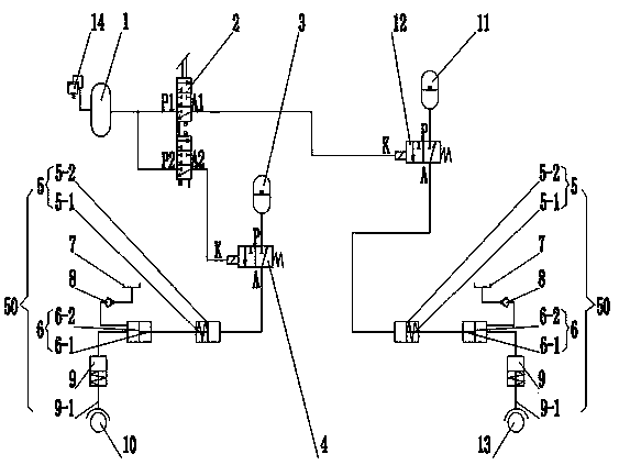
[0019] Such as figure 1 As shown, a vehicle booster brake device includes a brake mechanism 50, a front wheel brake 10 and a rear wheel brake 13, and the brake mechanism 50 includes a booster valve 5, a brake valve 6, an oil cup 7, an oil supply sheet The booster valve 5 has a first piston rod 5-1 and a first piston 5-2, and the brake valve 6 has a second piston rod 6-1 and a second piston 6 -2, the first piston rod 5-1 of the booster valve 5 is fixedly connected or integrated with the second piston rod 6-1 of the brake valve 6, and the oil cup 7 is connected to the brake valve through the oil supply check valve 8 The rodless chamber of the valve 6 is connected, and the rodless chamber of the brake valve 6 is connected with the rodless chamber of the brake cylinder 9, and the third piston rod 9-1 of the brake cylinder 9 is connected with the front whe...


PUM


Abstract

The invention relates to a braking method for a vehicle boost baking device. An adopted braking device comprises braking mechanisms, a front wheel brake and a rear wheel brake, wherein each of the braking mechanisms comprises a power-assisted valve, a braking vale, an oil cup, an oil complementing one-way valve and a braking cylinder; the braking device also comprises an air sac, a dual chamber air brake valve, a first energy accumulator, a first air controlled hydraulic valve, a second energy accumulator and a second air controlled hydraulic valve; the braking mechanisms are respectively connected to the front wheel brake and the rear wheel brake. The energy accumulators are used as power sources, so that boost braking after an engine flame out can be realized. An air passage is arranged between the dual chamber air brake valve and the air controlled hydraulic valve, so that the response speed of the brakes is high, and the phenomenon of slow braking is avoided. When the front wheel brake and the rear wheel brake are long in distance, the time difference of the front wheel brake and the rear wheel brake is short relatively, and the rear wheel brake is not obviously delayed; the braking performance is not influenced, so that traffic accidents cannot be caused.

Description

technical field [0001] The present invention relates to a braking device, in particular to a braking method for a vehicle booster braking device. Background technique [0002] As people pay more and more attention to the protection of the natural environment, pollution-free electric vehicles have become a popular direction. Due to the cancellation of the traditional fuel engine, the original vacuum booster loses vacuum and cannot assist braking. Chinese Patent Application No. 200810163260.5 discloses a hydraulic power-assisted braking device, which uses a hydraulic booster instead of a vacuum booster to solve the problem that the power-assisted braking cannot be performed due to the cancellation of the fuel engine, but the above-mentioned invention is driven by the engine. After the engine is turned off, the hydraulic pump will no longer work, so it will not be able to produce pressure oil. Therefore, when the engine is turned off, power-assisted braking cannot be achieved, ...

Claims


Application Information

Patent Timeline
Patent Type & Authority Patents(China)
IPC IPC(8): B60T13/14
CPCB60T13/12B60T13/14
Inventor 朱明德李成
Owner JIANGSU HENGLI BRAKE MFG
Why Eureka
Try Eureka