Transferring and furnace-entering device for refractory material and transferring and furnace-entering method for refractory material

A refractory material and furnace body technology is applied in the field of refractory material backward transport into the furnace device, which can solve the problems of low efficiency, high labor intensity and high breakage rate of refractory materials, and achieve high economic benefits, labor intensity reduction, and good stability.

Active Publication Date: 2016-10-12
河北二十冶建设有限公司
View PDF15 Cites 2 Cited by
  • Summary
  • Abstract
  • Description
  • Claims
  • Application Information

AI Technical Summary

Problems solved by technology

[0003] One of the purposes of the present invention is to provide a device for transporting refractory materials back into the furnace to solve the problems of high labor intensity, low efficiency and high damage rate of refractory materials in the existing transportation process

Method used


Image

  • Transferring and furnace-entering device for refractory material and transferring and furnace-entering method for refractory material

Examples


Embodiment 1

[0023] Embodiment 1: The refractory material is transported back into the furnace device.

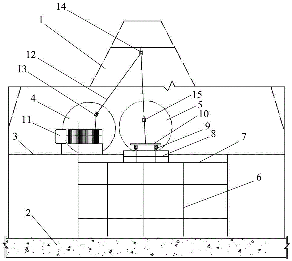
[0024] Such as figure 1 As shown, the device of the present invention is provided with a casthouse platform 2 and a tuyere platform 3 on the outside of the body of furnace 1, the tuyere platform 3 is located above the casthouse platform 2, and the furnace body 1 above the tuyere platform 3 is provided with a first The first tuyere 4 and the second tuyere 5 are provided with a steel frame structure on the inner wall of the furnace body 1 below the second tuyere 5 .

[0025] A scaffold 6 is set up on the casthouse platform 2, and the top of the scaffold 6 is located below the tuyere platform 3. A working platform 7 is laid on the top of the scaffolding 6, and the working platform 7 is formed by laying 20 channel steel, with smooth surface and stable structure. A track platform 8 is arranged on the working platform 7, one end of the track platform 8 is fixedly installed on the working pl...

Embodiment 2

[0027] Embodiment 2: The method of transporting the refractory material back into the furnace.

[0028] A, scaffolding 6 is built on the casting yard platform 2 of body of heater 1, and the top of scaffolding 6 is positioned at the below of tuyere platform 3 of body of heater 1; Work platform 7 is laid on the top of scaffold 6 built, and work platform 7 is made of 20 channel steel is laid, the surface is smooth and the structure is stable.

[0029] b. Set up a track platform 8 on the laid work platform 7, one end of the track platform 8 is fixedly installed on the work platform 7, and the other end enters the inside of the furnace body 1 through the second tuyere 5 on the furnace body 1, and is fixed on the On the inner wall of the furnace body 1 opposite to the second tuyere 5; at the same time, a walking platform for people to walk is set up on the side of the track platform 8, so that construction personnel can enter and exit the furnace body 1 inside and outside.

[0030]...


PUM


Abstract

The invention relates to a transferring and furnace-entering device for refractory material and a transferring and furnace-entering method for the refractory material. According to the device, a casting house platform and a tuyere platform are arranged on the outer side of a furnace body, and a first tuyere and a second tuyere are formed in the part, located above the tuyere platform, of the furnace body; a scaffold is erected on the casting house platform, a working platform is laid at the top of the scaffold and is provided with a track platform, the track platform penetrates through the second tuyere for entering the furnace body, and a transportation track is laid on the track platform and is provided with a track car; the tuyere platform is provided with a winching mechanism, and the winching mechanism is provided with a steel wire rope; a first fixed pulley is arranged on the inner side wall of the part, corresponding to the first tuyere, of the furnace body, a second fixed pulley is arranged at the top of the furnace body, a third fixed pulley is arranged on the inner side wall of the part, corresponding to the second tuyere, of the furnace body, and the steel wire is connected to the track car after sequentially winding around the three fixed pulleys. According to the device and the method, the transferring efficiency can be greatly improved, and the integrity of the refractory material can be guaranteed.

Description

technical field [0001] The invention relates to a reversing device and a reversing method, in particular to a refractory material reversing device and a refractory material reversing method. Background technique [0002] Blast furnace or shaft furnace is an important smelting equipment. The outer layer of the furnace body is a steel shell, and the inner layer is lined with refractory bricks. In the process of building a blast furnace or shaft furnace, the construction of refractory lining materials such as refractory bricks usually starts after the shell furnace skin and some equipment are installed. In the past, the refractory lining material was transported to the tuyere manually by a crane, and then transported to the inside of the blast furnace or shaft furnace. However, the above-mentioned method has a large amount of unloading work, high cost of machinery and equipment, and relatively slow speed, and during the unloading process, refractory bricks are easily damaged, ...

Claims


Application Information

Patent Timeline
Patent Type & Authority Applications(China)
IPC IPC(8): B65G35/00B65G65/32
CPCB65G35/00B65G65/32B65G2201/04
Inventor 李庆刚胡宝臣
Owner 河北二十冶建设有限公司
Why Eureka
Try Eureka