Novel stability control system for pile foundation in deep filling slope

A stability control system and slope technology, which is applied in landslide control and soil slope fields, can solve problems such as large engineering volume, limited anchoring force, and limited anti-sliding force, so as to speed up the project progress, reduce horizontal displacement, and ensure stability. Effect

Inactive Publication Date: 2016-10-12
CHONGQING JIAOTONG UNIVERSITY +1
View PDF7 Cites 7 Cited by
  • Summary
  • Abstract
  • Description
  • Claims
  • Application Information

AI Technical Summary

Problems solved by technology

However, the existing prevention and control methods and technologies all have problems such as large disturbance to the rock and soil mass of the slope, large amount of engineering, long time consumption, high cost, limited anti-sliding force that can be provided, and unsatisfactory reinforcement effect, etc.
Among them, anchoring is one of the commonly used and main technical measures in slope and landslide prevention and control engineering. It tightly interlocks the strata through the anchor rods buried in the strata; but the traditional anchoring method is fundamentally to provide The anchoring force indirectly prevents the slope from sliding through the anchoring force of the anchor instead of the anti-sliding force, and the anchoring force that can be provided is limited, so the reinforcement effect on the land structure slope formed by backfilling is not ideal
At the same time, rock and soil side slope landslide prevention projects are also affected by stratum lithology, rock and soil structure, geological structure, hydrogeology and other factors, and may be affected by strong earthquakes, posing a threat to project safety

Method used


Image

  • Novel stability control system for pile foundation in deep filling slope
  • Novel stability control system for pile foundation in deep filling slope

Examples


Embodiment Construction

[0016] The present invention will be further described below in conjunction with the accompanying drawings and embodiments, but it should not be understood that the scope of the subject matter of the present invention is limited to the following embodiments. Without departing from the above-mentioned technical ideas of the present invention, various replacements and changes made according to common technical knowledge and conventional means in this field shall be included in the protection scope of the present invention.

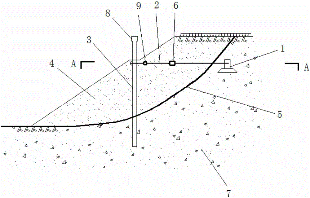
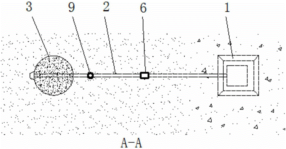
[0017] see figure 1 and figure 2 , this embodiment provides a new type of pile foundation stability control system for deep-filled slopes, including anchor piers 1, anchor rods 2, anti-slide piles 3 and tensioners 6. The anti-slide pile 3 is a vertically arranged cylindrical or rectangular reinforced concrete pile. The anti-slide pile 3 is arranged in the middle and lower part of the landslide area, wherein the landslide body 4 slides along the sliding su...


PUM


Abstract

The invention provides a novel stability control system for a pile foundation in a deep filling slope. The novel stability control system for the pile foundation in the deep filling slope comprises an anchorage pier, an anchor rod, a slide-resistant pile and a tension device. The slide-resistant pile is a vertically arranged reinforced concrete pile and arranged on the middle-lower portion of a slide slope zone. A slide slope body slides along a sliding surface. A lower layer of the sliding surface is a stabilized soil body or rock. The lower end of the slide-resistant pile goes deep into the stabilized soil body or the rock. The anchorage pier is buried into the stabilized soil body or the rock. The anchor rod is arranged perpendicular to the slide-resistant pile. One end of the anchor rod is fixed to the top end of the slide-resistant pile. The other end of the anchor rod horizontally penetrates through the slide slope body and is fixed inside the anchorage pier. The tension device is installed on the anchor rod and located inside the slide slope body. The novel stability control system for the pile foundation in the deep filling slope is simple in structure, convenient to construct, high in construction efficiency and capable of effectively preventing sliding of the slope.

Description

technical field [0001] The invention relates to soil slope and landslide control technology, in particular to a novel pile foundation stability control system for deep-filled slopes. Background technique [0002] At present, for the land structure formed by deep filling slope, the large deformation and instability of the backfill slope are one of the main controlling factors for the failure of normal use or even instability of the land structure. The deformation, failure mode and its scale have a decisive control effect. This is especially true when the angle of the original slope is within a certain range, or when a critical sliding surface is formed in the deep fill slope body, which plays an absolute control role in the stability of the slope body; because the backfill soil is relatively soft, the slope formed by backfill is more likely to appear Large deformation and instability, so slippage along the sliding surface of deep-filled slopes is the most important disease t...

Claims


Application Information

Patent Timeline
Patent Type & Authority Applications(China)
IPC IPC(8): E02D17/20
CPCE02D17/207E02D2600/30Y02A10/23
Inventor 刘明维李辉梁越王俊杰
Owner CHONGQING JIAOTONG UNIVERSITY
Why Eureka
Try Eureka