A method and device for gas recovery with plunger gas lift with velocity string and drainage

A velocity pipe string drainage and velocity pipe string technology, which is applied in the direction of production fluid, earthwork drilling, wellbore/well components, etc., can solve the problem that the wellbore fluid cannot be completely eliminated, and achieves low cost, simple method and improved effect Effect

Active Publication Date: 2018-06-01
PETROCHINA CO LTD
View PDF5 Cites 0 Cited by
  • Summary
  • Abstract
  • Description
  • Claims
  • Application Information

AI Technical Summary

Problems solved by technology

[0005] In order to overcome the problem that the existing tools cannot eliminate the liquid accumulation about 150m below the adapter, reduce the effect of plunger gas lift drainage gas recovery and gas well production, the present invention provides a plunger gas lift drainage gas recovery method with a velocity string And the device, the present invention solves the problem that the wellbore fluid accumulation cannot be completely eliminated by using the velocity pipe column drainage gas recovery or the plunger gas lift drainage gas recovery technology alone, and the method can solve the drainage gas recovery of the gas well in the entire life cycle from commissioning to abandonment The problem is that this method is simple, fast, and low in cost. It does not need to pull out the velocity string, and because the depth of the plunger is increased, it can improve the drainage and gas recovery effect of the plunger air lift alone.

Method used


Image

  • A method and device for gas recovery with plunger gas lift with velocity string and drainage
  • A method and device for gas recovery with plunger gas lift with velocity string and drainage
  • A method and device for gas recovery with plunger gas lift with velocity string and drainage

Examples


Embodiment 1

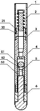
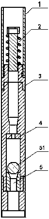
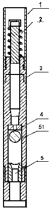
[0031] In order to overcome the problem that the existing tools cannot eliminate the accumulation of liquid about 150m below the adapter, and reduce the effect of the plunger gas lift drainage gas recovery and gas well production, the present invention provides: figure 1 Shown is a speed pipe string matching plunger gas lift drainage gas recovery method and device. The present invention solves the problem that the velocity pipe string drainage gas recovery or plunger gas lift drainage gas recovery technology alone cannot completely eliminate the wellbore fluid accumulation, and This method can solve the problem of drainage and gas recovery during the entire life cycle of a gas well from production to abandonment. The method is simple, fast, and low in cost. It does not require a riser speed string, and due to the increase in the depth of the plunger, the use of plungers can be improved. The drainage and gas recovery effect of gas lift.

[0032] A method for gas-lifting drainage an...

Embodiment 2

[0048] On the basis of Example 1, in this example, the step is to use the coiled tubing 1 with a diameter of 38.1 mm as the velocity string drainage gas production.

[0049] In the fifth step, when the gas production volume of the gas well is less than 2000m 3 / d, put a φ28mm ball plug 7 inside the speed column on the ground.

[0050] In the third step, the coiled tubing 1 is run into the wellbore by the coiled tubing operating machine and passed through the downhole tool until it runs to 8 m above the middle of the gas layer.

[0051] A speed pipe string supporting plunger gas lift drainage gas recovery device, comprising a buffer 2, a receiver 3, a spherical one-way valve 5 and a plug 6, the buffer 2, a receiver 3, a spherical one-way valve 5 and The plugs 6 are connected sequentially from top to bottom. The above-mentioned integrated devices are all preset to the bottom end of the coiled tubing 1; wherein the buffer 2 is internally locked and connected to the receiver 3, and the l...


PUM


Abstract

The invention provides a drainage and gas production method and device through velocity string in cooperation with plunger airlift. Coiled tubing is adopted as the velocity string for drainage and gas production; when the coiled tubing is introduced, a buffer, an adaptor, a spherical one-way valve and a packer are subjected to preconnection in sequence, and the connection bodies are connected with the velocity string in a rolling connection mode; a continuous string coiled tubing unit introduces the coiled tubing into a shaft and makes the coiled tubing penetrate a downhole tool, before well opening for production, a nitrogen boost truck is adopted to knock out the packer at the bottom of the coiled tubing, the coiled tubing serves as a production tubular column, and velocity string drainage and gas production are conducted. By means of the method and device, the problem that accumulated liquid in the shaft cannot be thoroughly eliminated by adopting the velocity string drainage and gas production technology or the plunger airlift drainage and gas production technology independently and the problem of drainage and gas production during the whole life cycle from production to abandon of a gas well are solved, the method is simple, fast and convenient to implement and low in cost, the velocity string does not need to be pulled out, and due to increase of the fed depth of a plunger, the drainage and gas production effect obtained by adopting plunger airlift independently can be improved.

Description

Technical field [0001] The present invention relates to the technical field of gas field exploitation, in particular to a method and device for gas-lift drainage and gas recovery with speed pipe string supporting plunger gas lift. The present invention is a drainage gas recovery for liquid-accumulated gas wells, which is a solution to the entire life cycle of gas wells from commissioning to abandonment The internal drainage gas recovery method is suitable for the entire life cycle drainage gas recovery of low-pressure, low-yield and easy-to-liquid gas wells. Background technique [0002] As the production time of the gas well continues, the productivity of the gas well gradually decreases. When the liquid-carrying flow rate is lower than the critical liquid-carrying flow rate, liquid begins to accumulate at the bottom of the well. If liquid drainage measures are not taken in time, the gas well may be flooded and stop production. Velocity string drainage gas recovery technology is...

Claims


Application Information

Patent Timeline
Patent Type & Authority Patents(China)
IPC IPC(8): E21B43/00E21B43/12
CPCE21B43/006E21B43/122
Inventor 赵彬彬付钢旦白晓弘刘双全汪雄雄李丽樊莲莲卫亚明杨丹丹
Owner PETROCHINA CO LTD
Why Eureka
Try Eureka