Exhaust passage of internal combustion engine and internal combustion engine with the same

An exhaust pipe, internal combustion engine technology, applied in the direction of internal combustion piston engine, combustion engine, machine/engine, etc., can solve the problems of structure and details of integrated exhaust pipe, and achieve the effect of improving heat discharge

Active Publication Date: 2016-10-12
VOLKSWAGEN AG
View PDF7 Cites 4 Cited by
  • Summary
  • Abstract
  • Description
  • Claims
  • Application Information

AI Technical Summary

Problems solved by technology

The document does not give information on how the cooling of the integrated exhaust duct should be constructed in detail

Method used


Image

  • Exhaust passage of internal combustion engine and internal combustion engine with the same
  • Exhaust passage of internal combustion engine and internal combustion engine with the same
  • Exhaust passage of internal combustion engine and internal combustion engine with the same

Examples


Embodiment Construction

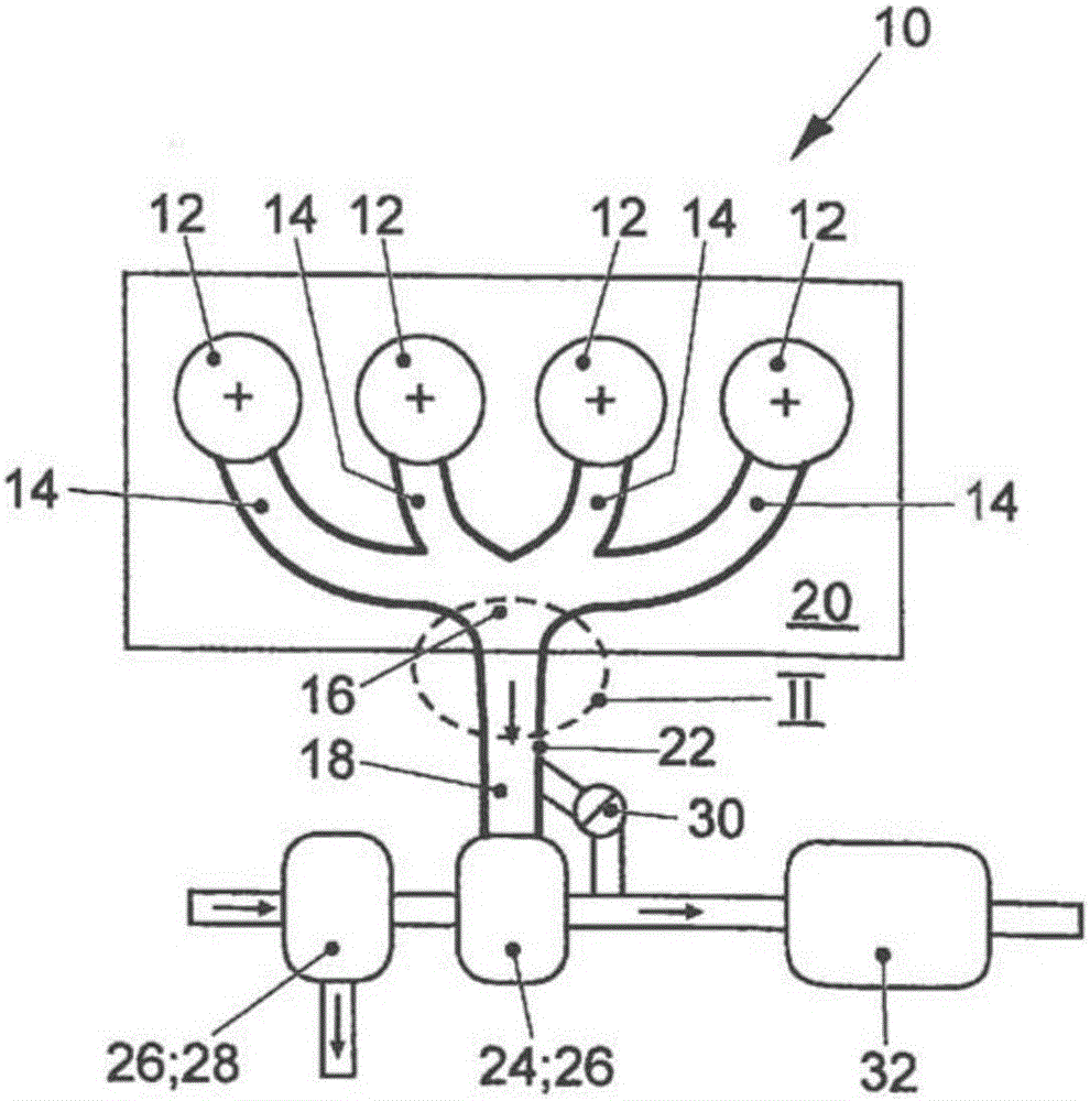
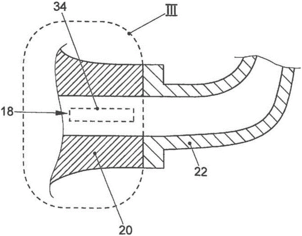
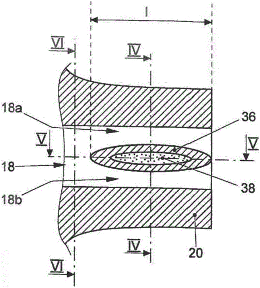
[0027] figure 1 Shown is an internal combustion engine 10 according to the invention with a total of four schematically illustrated cylinders 12 and exhaust gas lines 14 leading from these cylinders 12 , which join together at connection points 16 to a common (total) exhaust gas Tube 18. The connection point 16 is located within the schematically shown cylinder head 20 . Therefore, the exhaust pipe 18 is also referred to as an "integrated exhaust pipe". An intermediate element 22 , which leads to a turbine wheel 24 of an exhaust gas turbocharger 26 , is flanged to the cylinder head 20 . The exhaust gas turbocharger 26 also includes a compressor 28 . Such as figure 1 As shown, the exhaust gas can also be bypassed from the turbine 24 of the exhaust gas turbocharger 26 via a bypass valve 30 serving as a wastegate instead of via the turbine 24 . Arranged downstream of the turbine 24 is an exhaust gas aftertreatment system 32 , for example in the form of a three-way catalytic ...


PUM


Abstract

The invention relates to an exhaust gas passage of an internal combustion engine, in particular a reciprocating piston internal combustion engine with an exhaust gas turbocharger, as well as an internal combustion engine with such an exhaust gas passage. The invention is based on the object of providing an exhaust gas passage (18) of an internal combustion engine (10) as well as an internal combustion engine (10) which enables the exhaust gas of the internal combustion engine (10) to be efficiently cooled and thereby prevents the use of inexpensive materials in the area of flow components of downstream of such an internal combustion engine (10). In the exhaust gas passage (18) of the internal combustion engine (10) according to the invention with at least one coolant pipeline (38) for reducing the temperature of the exhaust gas of the internal combustion engine (10) flowing through the exhaust gas passage (18), at least one cooling structure (34) changing the cross section of the exhaust gas passage (18) is formed in partial region of the exhaust gas passage (18) and is operatively connected to the at least one coolant pipeline (38).

Description

technical field [0001] The invention relates to an exhaust gas line of an internal combustion engine, in particular a piston internal combustion engine with an exhaust gas turbocharger, and an internal combustion engine with such an exhaust gas line. Background technique [0002] Especially for externally ignited internal combustion engines with an exhaust gas turbocharger, the exhaust gas temperature first reaches very high values ​​in the range of rated power. This results in high loads on flow guide components, such as the exhaust gas tract and the turbine of the exhaust gas turbocharger, which is arranged downstream of the internal combustion engine. Due to the higher temperature requirements, in individual cases it is necessary to use high-temperature-resistant materials for individual elements of the flow-guiding element, which in turn are associated with high costs. [0003] It is known in practice to lower the exhaust gas temperature by accumulating, that is to say ...

Claims


Application Information

Patent Timeline
IPC IPC(8): F01N13/08F01N3/04F01N13/10F02F1/40F02F1/42
CPCF01N3/043F01N3/046F01N13/082F02F1/40F02F1/4264F01N13/10F01N2240/02F01N2260/024F01N2340/02F02B37/00F02F1/36F02F2001/4278Y02T10/12
Inventor P.舍勒
Owner VOLKSWAGEN AG
Why Eureka
Try Eureka