Mixed-flow turbosupercharger for integration vehicle

A turbocharger, integrated technology, applied in the direction of machines/engines, engine components, internal combustion piston engines, etc., can solve the problems of limited design, low price, reduce the risk of air leakage and deformation, and achieve a clear structure Simplicity, reliability, improved performance, flexible and fast assembly

Inactive Publication Date: 2016-10-12
奕森科技(上海)有限公司
View PDF8 Cites 2 Cited by
  • Summary
  • Abstract
  • Description
  • Claims
  • Application Information

AI Technical Summary

Problems solved by technology

[0006] Based on the above-mentioned background, in order to overcome the various drawbacks existing in the actual application process of the prior art, especially to overcome the defects such as poor cooling effect and high material cost (other defects are related to its technical solutions in other application documents of the applicant) specific elaboration), the present invention provides an integrated mixed-flow turbocharger for vehicles, by integrating the traditional turbine shell and bearing shell into an integrated turbine shell, omitting the connection between the traditional bearing shell and the turbine shell, The risk of air leakage and deformation is greatly reduced; furthermore, the improved integrated turbine casing effectively solves the problems of limited design of various components caused by structural limitations, and the cooling water channel can be cooled according to the best The effect is designed to avoid the occurrence of high temperature failure (cracking and damage of parts, coking of lubricating oil, etc.); more importantly, the new design method of the cooling water channel makes the material no longer limited to high-nickel cast stainless steel and other expensive materials. Aluminum and / or aluminum alloys and / or cast iron, etc. can also be used at a lower price

Method used


Image

  • Mixed-flow turbosupercharger for integration vehicle
  • Mixed-flow turbosupercharger for integration vehicle
  • Mixed-flow turbosupercharger for integration vehicle

Examples


Embodiment Construction

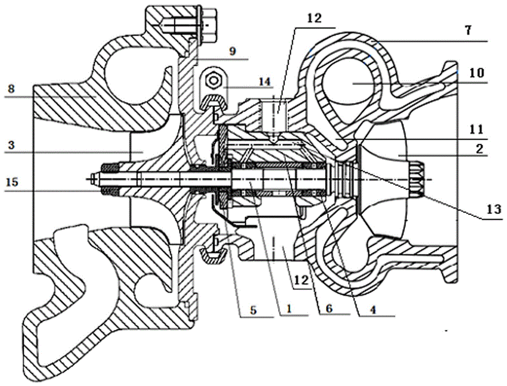
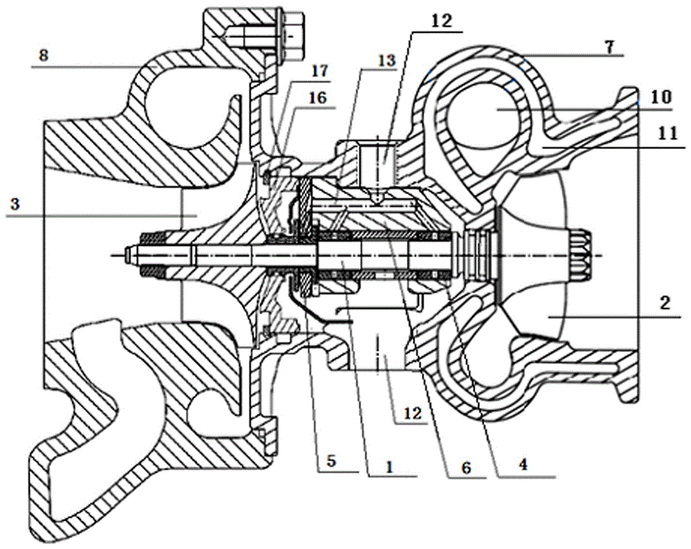
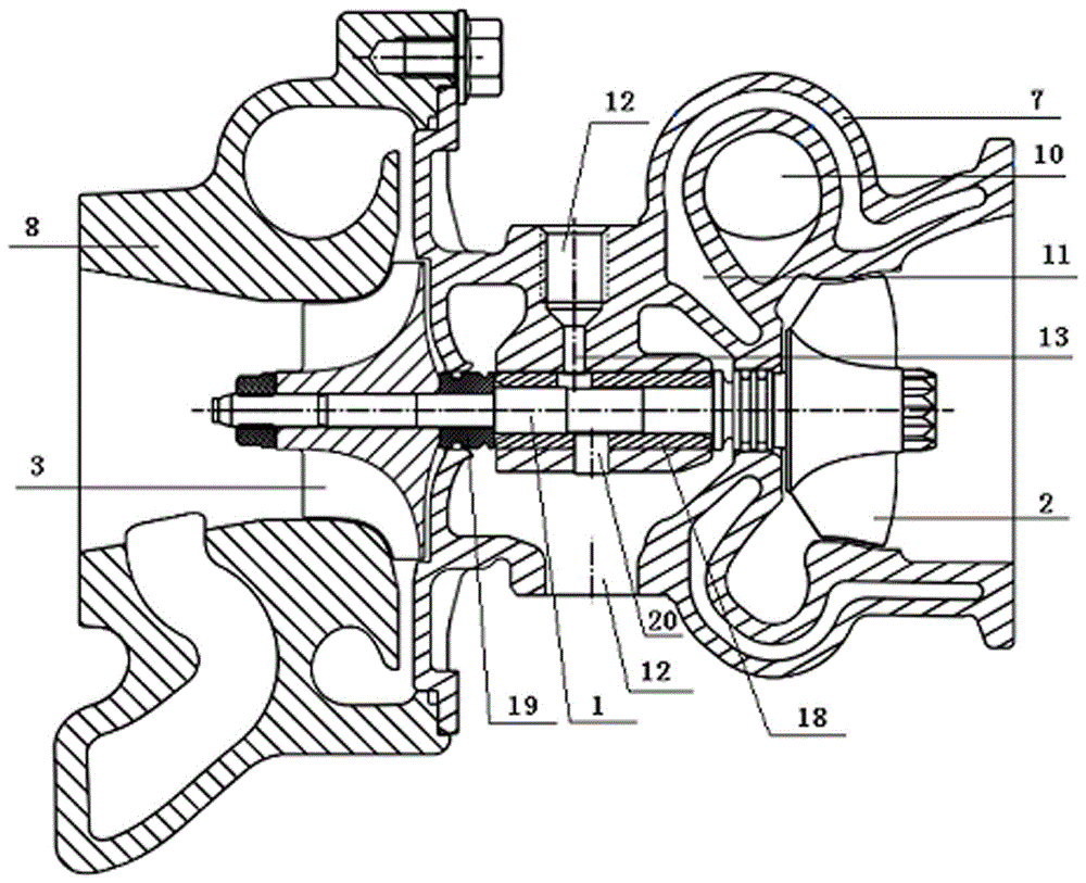
[0034]The invention provides an integrated mixed-flow turbocharger for a vehicle, which includes a rotating structure, a bearing structure, a bearing seat and a housing mechanism; the rotating structure includes a rotating shaft and turbines and impellers arranged at both ends of the rotating shaft; the The bearing structure includes a floating bearing and a thrust bearing ring arranged in the middle of the rotating shaft; the bearing seat is sleeved on the outside of the bearing structure; The integrated turbine casing, the impeller casing sleeved on the outside of the impeller, and the back plate connecting the integrated turbine casing and the impeller casing; wherein, the integrated turbine casing is provided with a vortex channel and a cooling water channel, so The cooling water channel is wrapped on the outside of the vortex channel.

[0035] The setting of the integrated turbine shell makes it possible for the cooling water channel to completely wrap the outer side of t...


PUM


Abstract

The invention provides a mixed-flow turbosupercharger for an integration vehicle. The mixed-flow turbosupercharger comprises a rotating structure, a bearing structure, a bearing pedestal and a shell mechanism; the rotating structure comprises a rotating shaft, a turbine and an impeller, the turbine and the impeller are arranged at the two ends of the rotating shaft, the bearing structure comprises a floating bearing and a thrust bearing which are annularly arranged on the middle portion of the rotating shaft, the outer side of the bearing structure is sleeved with the bearing pedestal, and the shell mechanism comprises an integration type turbine shell arranged on the outer side of the turbine and the outer side of the bearing pedestal in a sleeving manner, an impeller shell arranged on the outer side of the impeller in a sleeving manner and a back plate connecting the integration type turbine shell with the impeller shell; a turbine flow way and a cooling water way are arranged in the integration turbine shell, and the outer side of the turbine flow way is wrapped with the cooling water way; and a traditional turbine shell and a traditional bearing shell are integrated into the integration turbine shell, distribution of the cooling water way is designed, and the mixed-flow turbosupercharger has the outstanding beneficial effects and the obvious progress.

Description

technical field [0001] The invention relates to the field of vehicle machinery, in particular to a supercharger, in particular to an integrated vehicle mixed-flow turbocharger. Background technique [0002] During the development of the internal combustion engine, the application of turbocharging technology has played an important role in improving the specific power of the internal combustion engine and reducing the emission of the internal combustion engine. Judging from the current development of turbocharging technology, the radial flow turbocharger has reached a very high technical level. The specific speed of the type turbine is getting higher and higher, but its efficiency cannot reach the optimum value. If the specific speed is reduced, although this problem can be solved, it will increase the diameter of the impeller, thus affecting the performance of the supercharger. Transient responsiveness. In comparison, the mixed-flow turbocharger can not only improve the de...

Claims


Application Information

Patent Timeline
Patent Type & Authority Applications(China)
IPC IPC(8): F02B37/00F01D25/24F01D25/16F01D25/12
CPCF01D25/12F01D25/16F01D25/162F01D25/24F02B37/00Y02T10/12
Inventor 吴贺松熊劲松段景宏蒋向永
Owner 奕森科技(上海)有限公司
Why Eureka
Try Eureka