Integrated motor water pump

A water pump and shell technology, applied in the field of integrated motor water pump, can solve the problems of insufficient compact structure, single structure form, large volume, etc., and achieve the effect of increasing the effective water passage area and saving volume

Inactive Publication Date: 2016-10-12
刘兴国
View PDF6 Cites 5 Cited by
  • Summary
  • Abstract
  • Description
  • Claims
  • Application Information

AI Technical Summary

Problems solved by technology

[0002] In the existing fluid conveying equipment, the motor and the water pump are divided into two parts, which is not only costly, but also not compact enough in structure, especially in the axial direction, the volume is huge, and it is also necessary to consider whether the motor and the water pump match At present, some people try to combine the driving part of the water pump with the water pump body. For example, in the invention patent with application number 201410015550.0, the inventor directly sets the impeller on the motor shaft, and directly fixes the rotor of the motor or designs it in one piece. On the impeller, this structure is single and cannot replace most of the existing water pumps. At the same time, it is also difficult to realize multi-stage pumps with this structure. Therefore, it is necessary to provide a new integrated motor water pump structure.

Method used


Image

  • Integrated motor water pump
  • Integrated motor water pump
  • Integrated motor water pump

Examples


Embodiment Construction

[0015] Below will describe in detail according to the embodiment shown in accompanying drawing:

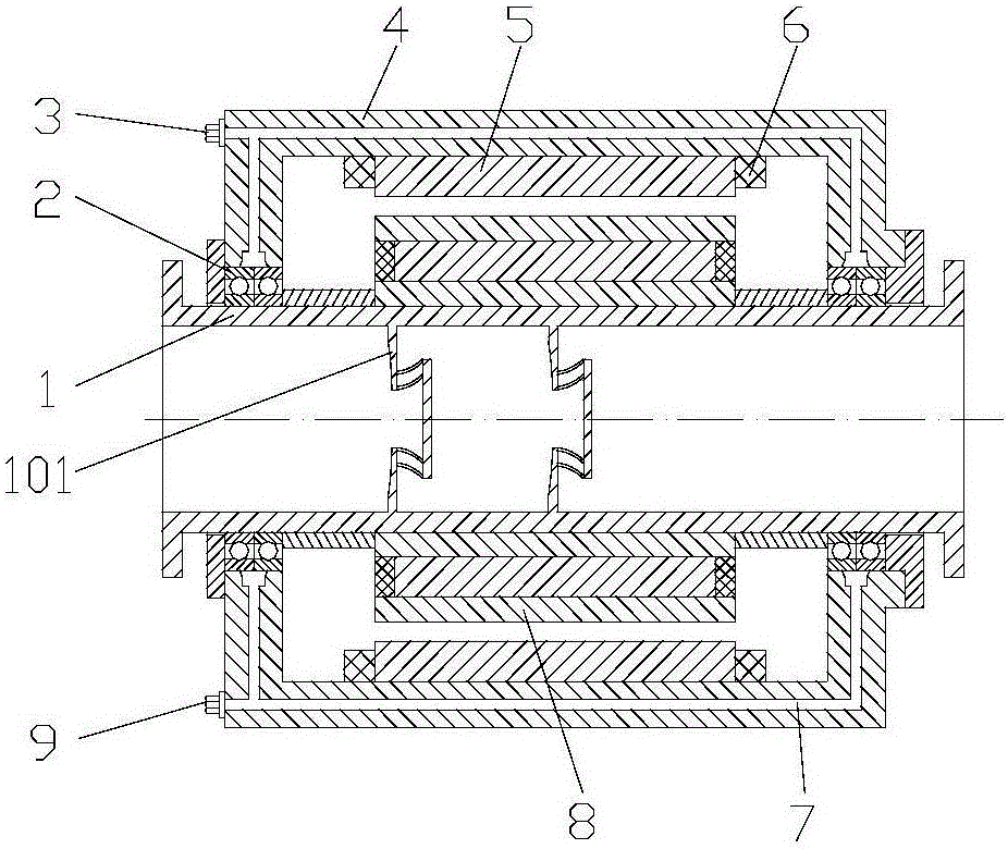
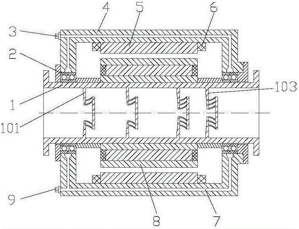
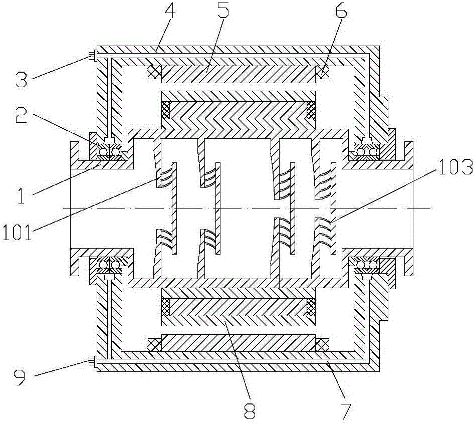
[0016] figure 1 It is a front view schematic diagram of an integrated motor water pump single-stage axial flow pump of the present invention, figure 2 It is a schematic diagram of the front view of an integrated motor water pump segmented multi-stage centrifugal water pump of the present invention, image 3 It is a schematic diagram of the front view of a segmented multistage centrifugal water pump when the inside of the rotating shaft of the integrated motor water pump of the present invention is stepped. It can be seen from the figure that an integrated motor water pump includes a rotor, a stator and a housing (4); the rotor shaft (1) is set on the centerline of the cylindrical housing (4) through a bearing, and The inner wall is provided with a stator core (5), and a stator winding (6) is wound on the stator core (5); the rotor shaft (1) is a hollow structure, that is, a thr...


PUM


Abstract

In existing fluid conveying equipment, a motor and a water pump are divided into two parts, consequently, cost is high, the structure is not compact, the size in the axis direction is particularly large, and the situation whether the motor and the water pump are matched or not needs to be considered as well. Therefore, a novel integrated motor water pump structure needs to be provided. An integrated motor water pump comprises a rotor, a stator and a shell. A rotor rotary shaft is arranged on the center line of the cylindrical shell through a bearing, a stator iron core is arranged on the inner wall of the shell, and a stator winding is wound around the stator iron core; and the rotor rotary shaft is of a hollow structure, in other words, a through hole is formed in the center of the rotor rotary shaft, and spiral blades protruding towards the central line of the rotary shaft are arranged at the middle section in the through hole.

Description

technical field [0001] The invention relates to the industry of general equipment for fluid transportation, in particular to an integrated motor water pump. Background technique [0002] In the existing fluid conveying equipment, the motor and the water pump are divided into two parts, which is not only costly, but also not compact enough in structure, especially in the axial direction, the volume is huge, and it is also necessary to consider whether the motor and the water pump match At present, some people try to combine the driving part of the water pump with the water pump body. For example, in the invention patent with application number 201410015550.0, the inventor directly sets the impeller on the motor shaft, and directly fixes the rotor of the motor or designs it in one piece. On the impeller, this structure is single and cannot replace most of the existing water pumps. At the same time, it is also difficult to realize multi-stage pumps with this structure. Therefor...

Claims


Application Information

Patent Timeline
Patent Type & Authority Applications(China)
IPC IPC(8): F04D13/06F04D1/06F04D3/00F04D29/18F04D29/24H02K7/00
CPCF04D13/06F04D1/06F04D3/00F04D29/181F04D29/242H02K7/003
Inventor 刘兴国
Owner 刘兴国
Why Eureka
Try Eureka