
Differential device

一种差动装置、差动齿轮的技术,应用在差速传动装置、传动装置、传动装置零件等方向,能够解决供给油量少、旋转滑动部润滑不足、润滑效果不充分等问题,达到高效捕捉积存的效果

Active Publication Date: 2016-10-12
MUSA PRECISION IND CO LTD
View PDF13 Cites 4 Cited by
  • Summary
  • Abstract
  • Description
  • Claims
  • Application Information

AI Technical Summary

Problems solved by technology

[0007] However, in the conventional device, the lubricating oil introduced between the opposing surfaces of the pair of side gears tends to flow radially outward along the opposing surfaces due to centrifugal force, and therefore, most of the introduced lubricating oil flows directly to the opposing surfaces. Face connected to the outer circumference of the side gear to the side flow of the gear part
Therefore, the lubricating effect on the meshing portion of the side gear and the pinion is sufficiently obtained, but there is a problem that the amount of oil supplied to the above-mentioned oil reservoir is relatively small, and the fitting portion between the pinion and the pinion shaft, that is, Insufficient lubrication of rotating and sliding parts
[0008] Furthermore, regarding the insufficient lubrication of the rotating and sliding part between the pinion and the pinion shaft, for example, the diameter of the side gear is sufficiently larger than that of the pinion so that the number of teeth of the side gear can be set sufficiently larger than that of the small gear. When the number of teeth of the gear is narrowed in the axial direction of the output shaft of the differential case, etc., it may be more obvious especially in severe operating conditions where the pinion rotates at a high speed.

Method used


Image

  • Differential device
  • Differential device
  • Differential device

Examples


Embodiment Construction

[0042] Hereinafter, embodiments of the present invention will be described with reference to preferred embodiments of the present invention shown in the accompanying drawings.

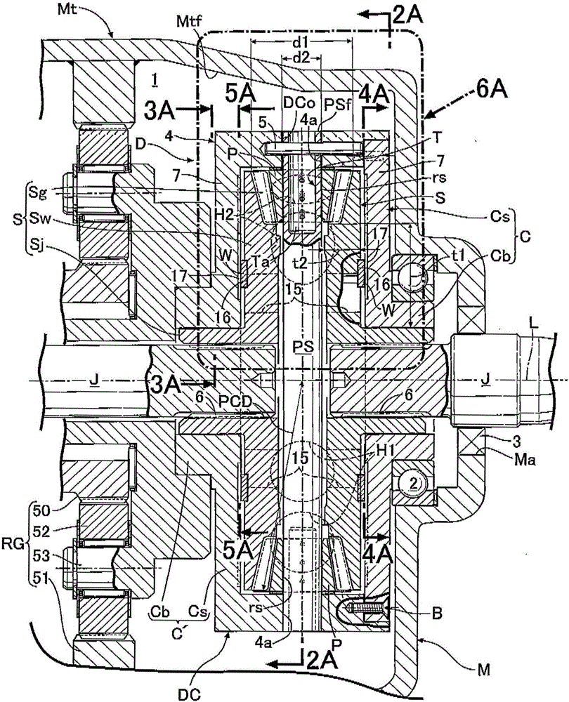
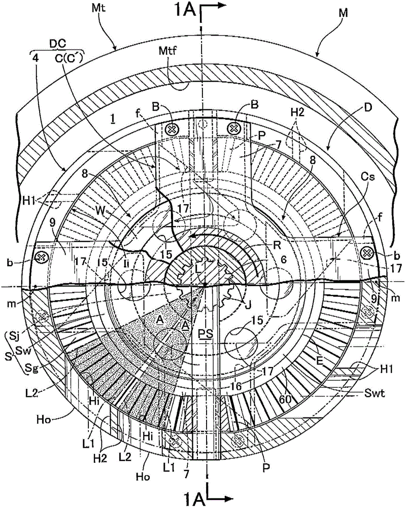
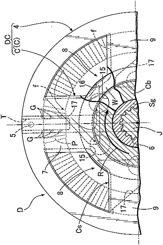
[0043] First, in figure 1 In this case, a differential device D is connected to an engine (not shown) as a power source mounted on an automobile via a reduction gear mechanism RG. The differential device D distributes and transmits the rotational force transmitted from the engine to the differential case DC via the reduction gear mechanism RG to the left and right pair of output shafts J respectively connected to the left and right pair of axles, thereby allowing the difference between the left and right axles. The left and right axles are dynamically and rotationally driven. For example, the differential device D is accommodated in a transmission M arranged next to the engine at the front of the vehicle body together with the reduction gear mechanism RG in a state adjacent to the reduction gear mechan...


PUM


Abstract

A differential device includes pinion; pinion shaft; paired side gears connected to paired output shafts and having at outer peripheral portions gear portions meshing with the pinion; and oil introduction passage introducing lubricant oil to mutually-facing surfaces of the side gears. An oil reserving portion facing space adjacent to end surface of the pinion on radially inner side and capable of catching and holding lubricant oil splashed to the space is formed in portion where the pinion and the pinion shaft mutually face, so as to communicate with fitting portion between the pinion and the pinion shaft where they are relatively rotationally slidable. A step portion is formed in at least one of the mutually-facing surfaces, separates part of oil from lubricant flow flowing radially outward along the one surface by centrifugal force, and guides the oil into the space.

Description

technical field [0001] The present invention relates to a differential device that distributes and transmits rotational force of a differential case to a pair of output shafts. Background technique [0002] There is a differential device including: a pinion (differential gear) disposed in a differential case; a pinion shaft (differential gear support portion) supported by the differential case and and a pair of side gears (output gears) each having a gear part meshing with a pinion on the outer peripheral part, and the pair of side gears are opposed to each other with the pinion shaft in between, and are respectively connected to a Connected to the output shafts, the differential device distributes and transmits the rotational force of the differential housing to the pair of output shafts. Conventionally, as described in Patent Document 1, the following differential device is known for such a differential device: : An oil storage part is provided at the opposing part of the...

Claims


Application Information

Patent Timeline
Patent Type & Authority Applications(China)
IPC IPC(8): F16H57/04F16H57/037
CPCF16H57/037F16H57/042F16H48/08F16H57/0427F16H57/0457F16H57/0483
Inventor 森裕之
Owner MUSA PRECISION IND CO LTD
Learn More