Diaphragm type pilot control solenoid valve

A pilot control and solenoid valve technology, applied in the field of solenoid valves, can solve the problems of large movement stroke of the pilot valve core iron, increase the diameter of the valve port, and difficult processing, achieve the maximum allowable working pressure difference, and reduce the coil power. requirements and achieve the effect of miniaturization

Inactive Publication Date: 2016-10-12
浙江盈亿机械股份有限公司
View PDF7 Cites 0 Cited by
  • Summary
  • Abstract
  • Description
  • Claims
  • Application Information

AI Technical Summary

Problems solved by technology

[0005] In the prior art, the patent CN200620100262 discloses a seal A type solenoid valve used in refrigeration and industrial applications to control the flow of medium. The pilot valve port of the solenoid valve is connected to the seal A that seals the main valve port. At the same time, in this way, the movement stroke of the pilot valve core iron will become larger with the increase of the aperture of the main valve port, so the power requirement for the supporting coil is greater, the cost is higher, and the product cannot be compact
[0006] In another prior art, the patent CN200420110999 discloses a large-diameter pilot solenoid valve. As mentioned above, the main valve of a typical pilot solenoid valve is related to the stroke of the pilot valve. As the diameter of the main valve increases, The power of the coil also increases. The structure of the patented valve body adopts a structure in which the main valve and the pilot valve are separated. On the premise of not increasing the power of the coil, the diameter of the valve port is effectively increased. However, the valve body of the solenoid valve Complex structure, difficult processing

Method used


Image

  • Diaphragm type pilot control solenoid valve
  • Diaphragm type pilot control solenoid valve
  • Diaphragm type pilot control solenoid valve

Examples


Embodiment 1

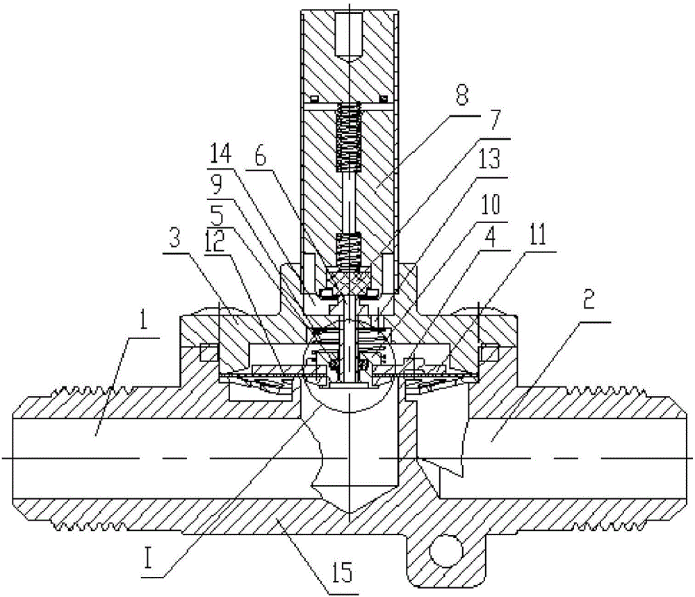
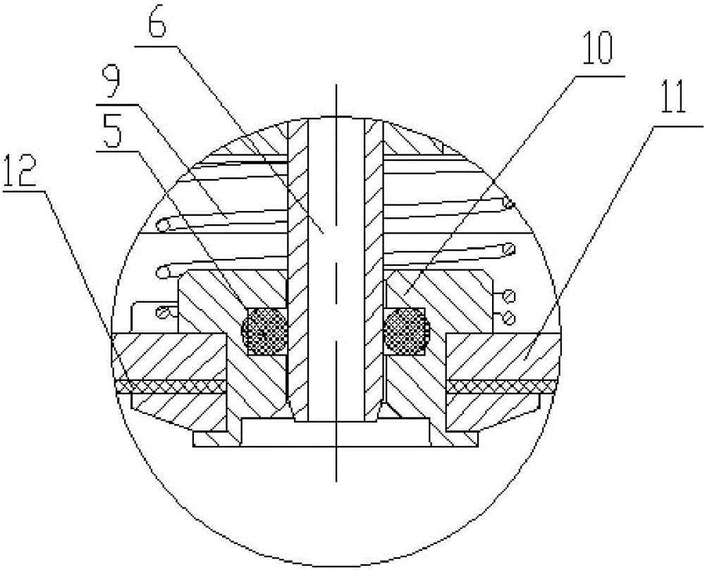
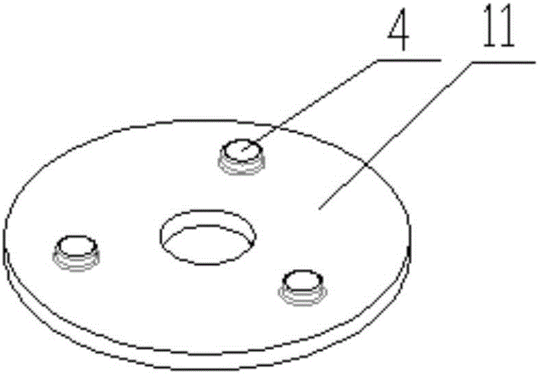
[0027] like figure 1 , figure 2 and image 3 The diaphragm type pilot control solenoid valve shown includes a valve seat 15, and a valve cover 3 is arranged on the upper part of the valve seat 15; The valve seal 7; the middle part of the valve cover 3 is provided with a conduction piece 6; the side of the lower part of the conduction piece 6 is provided with a mandrel sleeve 10, and the outer side of the mandrel sleeve 10 is provided with a movement limiter 11; the lower part of the movement limiter 11 is set There is a seal A12; a seal B5 is provided between the lower part of the movement limiter 11 and the conduction member 6; a return spring 9 is provided between the outside of the conduction member 6 and the movement limiter 11; Hole 13; valve cover 9 upper part is provided with pilot valve chamber 14. A plurality of protrusions 4 are arranged on the upper part of the movement limiting member 11 . The left and right sides of the valve seat 15 are respectively provided...

Embodiment 2

[0034] like Figure 4 and Figure 5 The diaphragm type pilot control solenoid valve shown includes a valve seat 15, and a valve cover 3 is arranged on the upper part of the valve seat 15; The valve seal 7; the middle part of the valve cover 3 is provided with a conduction piece 6; the side of the lower part of the conduction piece 6 is provided with a mandrel sleeve 10, and the outer side of the mandrel sleeve 10 is provided with a movement limiter 11; the lower part of the movement limiter 11 is set There is a seal A12; a seal B5 is provided between the lower part of the movement limiter 11 and the conduction member 6; a return spring 9 is provided between the outside of the conduction member 6 and the movement limiter 11; Hole 13; valve cover 9 upper part is provided with pilot valve chamber 14. A plurality of protrusions 4 are arranged on the upper part of the movement limiting member 11 . The left and right sides of the valve seat 15 are respectively provided with a val...

Embodiment 3

[0042] like Image 6 and Figure 7 The diaphragm type pilot control solenoid valve shown includes a valve seat 15, and a valve cover 3 is arranged on the upper part of the valve seat 15; The valve seal 7; the middle part of the valve cover 3 is provided with a conduction piece 6; the side of the lower part of the conduction piece 6 is provided with a mandrel sleeve 10, and the outer side of the mandrel sleeve 10 is provided with a movement limiter 11; the lower part of the movement limiter 11 is set There is a seal A12; a seal B5 is provided between the lower part of the movement limiter 11 and the conduction member 6; a return spring 9 is provided between the outside of the conduction member 6 and the movement limiter 11; Hole 13; valve cover 9 upper part is provided with pilot valve cavity 14. A plurality of protrusions 4 are arranged on the upper part of the movement limiting member 11 . The left and right sides of the valve seat 15 are respectively provided with a valve...


PUM


Abstract

The invention relates to a diaphragm type pilot control solenoid valve. The diaphragm type pilot control solenoid valve comprises a valve seat; a valve cover is arranged at the upper part of the valve seat; pilot valve core iron is arranged at the intermediate position of the upper part of the valve cover; a pilot valve sealing piece is arranged at the bottom position of the pilot valve core iron; a conducting piece is arranged at the intermediate position of the valve cover; a mandrel sleeve is arranged on the outer side of the conducting piece; a movement limiting piece is arranged on the outer side of the mandrel sleeve; a sealing piece A is arranged at the lower part of the movement limiting piece; a sealing piece B is arranged between the lower part of the movement limiting piece and the conducting piece; a return spring is arranged between the outer side of the conducting piece and the movement limiting piece; a through hole is formed in the valve cover; a pilot valve cavity is formed in the upper part of the valve cover. A plurality of bulges are formed at the upper part of the movement limiting piece. A valve body inlet and a valve body outlet are respectively formed in the left side and the right side of the valve seat. According to the diaphragm type pilot control solenoid valve, the valve body is compact and the flow resistance of a pilot valve flow path can also be reduced, so that the valve body can obtain a greater allowable maximum operating pressure difference.

Description

technical field [0001] The invention relates to a diaphragm type pilot control solenoid valve, which belongs to the technical field of solenoid valves. Background technique [0002] The field of control valves often involves solenoid valves to control the on-off of the medium in the system. According to different functional requirements in the system, it can be divided into normally open type and normally closed type. According to the internal structure of the solenoid valve, it can be divided into direct-acting type and Pilot-operated, pilot-operated solenoid valves often need to drive a small orifice (pilot valve) inside the solenoid valve through the electromagnetic coil. When the pilot valve is opened, the sealing moving parts sealed on the larger orifice will be affected by the pressure difference. Open the larger valve port (main valve) at the bottom, so as to realize the function of medium on-off in the control system. [0003] In recent years, with the intensificati...

Claims


Application Information

Patent Timeline
Patent Type & Authority Applications(China)
IPC IPC(8): F16K31/06
CPCF16K31/0655
Inventor 李志斌王锦江
Owner 浙江盈亿机械股份有限公司
Why Eureka
Try Eureka