Non-contact magnetic coding sensor

A magnetic encoder and magnetic encoding technology, applied in the field of measurement, can solve the problems of complex structure and low measurement accuracy, and achieve the effects of high measurement accuracy, simple process and long life

Inactive Publication Date: 2016-10-12
SHANGHAI JUNQIAN SENSING TECH CO LTD
View PDF4 Cites 8 Cited by
  • Summary
  • Abstract
  • Description
  • Claims
  • Application Information

AI Technical Summary

Problems solved by technology

[0013] Aiming at the common problems of complex structure and low measurement accuracy in commonly used encoders for measuring rotating objects, the main purpose of the present invention is to provide an absolute magnet

Method used


Image

  • Non-contact magnetic coding sensor
  • Non-contact magnetic coding sensor
  • Non-contact magnetic coding sensor

Examples


Embodiment Construction

[0042] In order to make the technical means, creative features, goals and effects achieved by the present invention easy to understand, the present invention will be further described below in conjunction with specific illustrations.

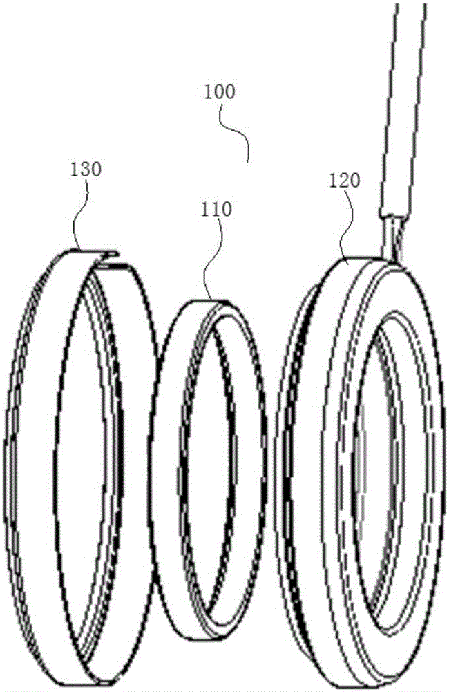
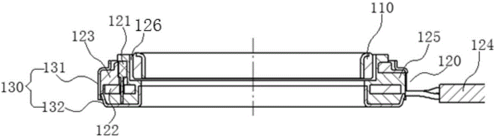
[0043] see figure 1 and 2 , which shows the basic structural structure of the non-contact magnetic encoder sensor in the example of the present invention.

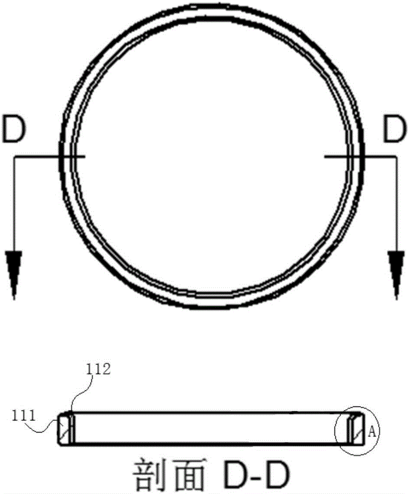
[0044] It can be seen from the figure that the non-contact magnetic encoder sensor 100 in this example has a circular shape as a whole and mainly includes three parts: an annular magnetic encoder 110 , an annular sensor body assembly 120 and a metal casing 130 .

[0045] Wherein, the annular magnetic encoder 110 is non-contact embedded in the annular sensor body assembly 120 , and can rotate in the sensor body assembly 120 along with the target object; and the metal shell 130 is arranged outside the sensor body assembly 120 .

[0046] In the non-contact magnetic encoder sensor 100 thus con...


PUM


Abstract

The invention discloses a non-contact magnetic coding sensor, which mainly comprises a magnetic encoder and a sensor body assembly, and is characterized in that the magnetic field of the magnetic encoder in one period is in sine distribution, and the sensor body assembly acquires a vibration magnetic field generated by rotating the magnetic encoder and correspondingly outputs a path of sine analog signals and a path of cosine analog signals. The non-contact absolute type magnetic coding sensor provided by the invention can accurately measure the speed and the absolute position of a rotating object, and can detect the rotating direction at the same time. Meanwhile, the magnetic coding sensor is high in measurement accuracy, short in response time, simple in process, long in service life and capable of operating in a high-temperature oil pollution environment.

Description

technical field [0001] The invention relates to a measurement technology, in particular to a magnetically coded sensor. Background technique [0002] According to the detection principle, the commonly used encoders for measuring rotating objects can be divided into optical, magnetic, inductive and capacitive. [0003] A photoelectric encoder is a sensor that converts the mechanical geometric displacement on the output shaft into pulse or digital quantity through photoelectric conversion. Light-transmitting and opaque lines are regularly engraved on the disc, and light-emitting elements and photosensitive elements are placed on both sides of the disc. When the disc rotates, the luminous flux received by the photosensitive element changes synchronously with the light-transmitting lines, and the output waveform of the photosensitive element becomes a pulse after being shaped. There is a phase mark on the code disc, and a pulse is output for each revolution. In addition, in or...

Claims


Application Information

Patent Timeline
IPC IPC(8): G01D5/14G01D5/16
CPCG01D5/142G01D5/16
Inventor 姜泽明
Owner SHANGHAI JUNQIAN SENSING TECH CO LTD
Why Eureka
Try Eureka