Young modulus measuring method achieved through metal wire drawing method

A technology of Young's modulus and measurement method, which is applied in the direction of measuring device, using stable tension/pressure to test the strength of materials, instruments, etc., can solve the problems of tape bending, difficulty in accuracy, measurement error, etc., and achieve cost saving and convenience Measuring, reducing the effect of conditioning steps

Inactive Publication Date: 2016-10-12
SICHUAN UNIV
View PDF5 Cites 7 Cited by
  • Summary
  • Abstract
  • Description
  • Claims
  • Application Information

AI Technical Summary

Problems solved by technology

[0003] The length measurement of the metal wire is inaccurate: because the upper end and the lower end of the metal wire are clamped by the clamp, the upper end clamp is fixed on the support plate of a support frame, and the lower end clamp is located in the center hole of the support plate in the middle of the support frame. The effective length of the root wire (the distance between the fixed point of the upper clamp and the fixed point of the lower clamp) is different. When measuring the length of the wire, the tape measure used to measure the wire is affected by the angle between the surface of the wire clamp and the wire at approximately 90 degrees. If the tape is close to the steel wire, the tape will bend and cannot be close to the fixed point between the steel wire and the fixture, resulting in large errors in measurement
[0004] Measuring the elongation of the metal wire with a polished rod is more complicated: a vertical ruler is fixed next to the telescope, the upper surface of the lower end fixture of the steel wire fixes the rear feet of the polished rod, and the fulcrum (two front legs) of the polished rod is located in the middle of the support frame. On the support plate, there is a rotatable plane mirror above the t...

Method used


Image

  • Young modulus measuring method achieved through metal wire drawing method

Examples


Embodiment Construction

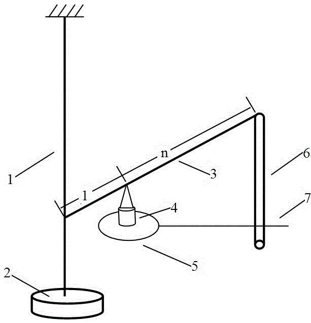
[0010] Metal wire stretching method Young's modulus measurement method, the upper end of a metal wire 1 (the object to be measured Young's modulus) is fixed on the support frame (that is, the upper end is fixed, the existing Young's modulus measurement, The upper end is generally fixed on the beam at the upper end of the support frame, and some are also fixed on the ceiling, which can be realized by the prior art), and a tray 2 is fixed on the lower end, and the tray 2 is used to add heavy objects (the prior art is to add or Reduce the weight, each weight is generally 1 kg), and the fixed point is located in the center of the tray.

[0011] A lever 3, one end of the lever 3 is clamped on the wire, because the lever itself is not strong, only a scale 6 (or called a scale) is hung on the right end, according to the similarity of the triangle, the purpose of the lever It only enlarges the elongation of the metal wire on the left, so the force between the lever and the metal wire ...


PUM


Abstract

The invention provides a Young modulus measuring method achieved through a metal wire drawing method, and relates to physical parameter measuring. According to the technical scheme for simplifying Young modulus measuring, the upper end of a metal wire is fixed, and a tray is fixed to the lower end of the metal wire; one end of a lever is clamped on the metal wire, a support point of the lever is fixed to the upper end of a support, and the lever can rotate around the support point; a cylindrical scale is hung at the tail end of the lever; a horizontal slender rod stretches out of a fixing platform, and the tail end of the right side of the horizontal slender rod is in a cylindrical shape and is used as a reading pointer; the diameter d of the metal wire is measured, the distance L between the fixing point of the lever on the metal wire and the upper end fixing point of the metal wire is measured, the magnification times n of the lever is measured, the reading number x1 of the scale is read through the position where the slender rod points, a weight with the mass of m is added on the tray, the scale reading number x2 of the position where the slender rod points is read again, and then the Young modulus Y=4 m*g*n*L/(pi*d<2>*|x2-x1|) is obtained, wherein g is the gravity acceleration, and pi is the circumference ratio. The method has the advantages that the cost is reduced, and regulation is convenient.

Description

technical field [0001] The invention relates to the field of measurement of physical parameters, especially the measurement of Young's modulus of materials. Background technique [0002] The measurement of Young's modulus of metal wire is a common experiment in university physics experiments. It mainly uses the principle of optical lever amplification to measure the elongation of steel wire, so as to calculate the Young's modulus of steel wire. The parameters that must be measured are: the length of the wire, the diameter of the wire, the elongation of the wire, the mass of the added weight (use weights, the mass of 1 weight is 1 kg, generally use 8-9 Weights), the shortcomings of which are: [0003] The length measurement of the metal wire is inaccurate: because the upper end and the lower end of the metal wire are clamped by the clamp, the upper end clamp is fixed on the support plate of a support frame, and the lower end clamp is located in the center hole of the support...

Claims


Application Information

Patent Timeline
IPC IPC(8): G01N3/14
CPCG01N3/14G01N2203/0003G01N2203/0017G01N2203/0033G01N2203/0098G01N2203/0252G01N2203/028G01N2203/0605G01N2203/0682
Inventor 雍志华胡再国
Owner SICHUAN UNIV
Why Eureka
Try Eureka