Method for sinter microstructure analysis based on panoramic mineral phase diagram

A technology of microstructure and analysis method, which is applied to the analysis of materials, material analysis through optical means, instruments, etc. It can solve the problems of heavy workload, limited observation field of view, and high price of microscopes, and achieve the effect of improving quality and improving quality

Inactive Publication Date: 2016-10-12
WUHAN UNIV OF SCI & TECH
View PDF4 Cites 7 Cited by
  • Summary
  • Abstract
  • Description
  • Claims
  • Application Information

AI Technical Summary

Problems solved by technology

[0003] Most of the sinter mineral phase identification commonly used by researchers at home and abroad is based on a single microscopic image. Ordinary optical microscopes do not have the function of automatic splicing, and the observation field of view is limited. It is difficult to fully reflect the microstructure information of sinter ore. Manual splicing It is a cumbersome, experience-dependent and very heavy workload, and the price of microscopes with automatic stitching function on the market is relatively high

Method used


Image

  • Method for sinter microstructure analysis based on panoramic mineral phase diagram
  • Method for sinter microstructure analysis based on panoramic mineral phase diagram
  • Method for sinter microstructure analysis based on panoramic mineral phase diagram

Examples


Embodiment 1

[0053] 1) Sample preparation and polishing. The sintered ore of WISCO was used in this example, and its chemical composition is shown in Table 1. The sample is roughly ground, hot-mounted, polished, dried, and observed under a microscope.

[0054] Table 1 The chemical composition of the iron-containing charge used in the experiment

[0055] Mineral

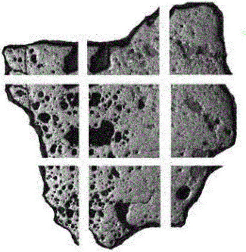
[0056] 2) Image collection: Use a low magnification (40×) optical microscope to capture image information with a camera. Fix the sample, choose to start from the upper left corner of the sample to take the first shot, then make 2 unidirectional movements in the X direction, and take a shot after each movement. Then the microscope moves to the first shooting area, performs one unidirectional movement in the Y direction and takes pictures, and then performs two unidirectional movements in the X direction, and takes pictures after each movement. Repeat with a second unidirectional move in the Y direction and shoot, then ...

Embodiment 2

[0062] 1) Sample preparation and polishing. The sintered ore of WISCO was used in this example, and its chemical composition is shown in Table 2. The sample is roughly ground, hot-mounted, polished, dried, and observed under a microscope.

[0063] Table 1 The chemical composition of the iron-containing charge used in the experiment

[0064] Mineral

[0065]2) Image collection: Use a low magnification (40×) optical microscope to capture image information with a camera. Fix the sample, choose to start from the upper left corner of the sample to take the first shot, then make 2 unidirectional movements in the X direction, and take a shot after each movement. Then the microscope moves to the first shooting area, performs one unidirectional movement in the Y direction and takes pictures, and then performs two unidirectional movements in the X direction, and takes pictures after each movement. Repeat with a second unidirectional move in the Y direction and shoot, then 2...

Embodiment 3

[0071] 1) Sample preparation and polishing. The sintered ore of WISCO was used in this example, and its chemical composition is shown in Table 3. The sample is roughly ground, hot-mounted, polished, dried, and observed under a microscope.

[0072] Table 1 The chemical composition of the iron-containing charge used in the experiment

[0073] Mineral

[0074] 2) Image collection: Use a low magnification (40×) optical microscope to capture image information with a camera. Fix the sample, choose to start from the upper left corner of the sample to take the first shot, then make 2 unidirectional movements in the X direction, and take a shot after each movement. Then the microscope moves to the first shooting area, performs one unidirectional movement in the Y direction and takes pictures, and then performs two unidirectional movements in the X direction, and takes pictures after each movement. Repeat with a second unidirectional move in the Y direction and shoot, then ...


PUM


Abstract

The invention belongs to the technical field of sinter mineral phase analysis and particularly relates to a method for sinter microstructure analysis based on a panoramic mineral phase diagram. The method comprises a step S10 of shooting the surface of a designated area of a sinter sample to obtain a digital photo set, and storing the digital photo set to be an electronic photo set; a step S20 of using a median filtering method to perform smoothing on each digital photo in the electronic photo set obtained in the step S10; a step S30 of performing splicing fusion on the electronic photo set obtained in the step S30 to obtain a panoramic mineral phase diagram of sinter; a step S40 of performing image segmentation on local images of the panoramic mineral phase diagram obtained in the step S30, respectively calculating pixel proportions of different mineral phases in the local images, and obtaining the proportion of each mineral phase. According to the method, the way of comprehensively and deeply analyzing the sinter microstructure is provided, and the basis is provided for searching the mineralization mechanism and solution and improving sinter products and quality.

Description

technical field [0001] The invention belongs to the technical field of mineral phase analysis of sintered ore, and in particular relates to a method for analyzing the microstructure of sintered ore based on a panoramic mineral phase diagram. Background technique [0002] At present, steel production capacity is overcapacity, iron ore prices are rising, the profit margins of steel enterprises are narrowing, and the pressure of survival is increasing. Low-priced, low-grade ore. It is of great significance to analyze the mineral composition and microstructure of sinter, which is conducive to saving energy, reducing economic costs and reducing environmental pollution. [0003] Most of the sinter mineral phase identification commonly used by researchers at home and abroad is based on a single microscopic image. Ordinary optical microscopes do not have the function of automatic splicing, and the observation field of view is limited. It is difficult to fully reflect the microstruc...

Claims


Application Information

Patent Timeline
Patent Type & Authority Applications(China)
IPC IPC(8): G01N21/84
CPCG01N21/84
Inventor 王炜欧阳泽林武风楼徐润生黄小波薛正良蔡路军
Owner WUHAN UNIV OF SCI & TECH
Why Eureka
Try Eureka