Automatic-rise-fall computer display device bracket

A display stand and automatic lifting technology, which is applied in the direction of machines/stands, instruments, supporting machines, etc., can solve the problem of inability to accurately control the distance of rising and falling, the time of rising, falling and stopping, and the inability to adjust Issues such as speed of ascent and descent

Pending Publication Date: 2016-10-12
叶建新
View PDF4 Cites 11 Cited by
  • Summary
  • Abstract
  • Description
  • Claims
  • Application Information

AI Technical Summary

Problems solved by technology

[0003] 1. It is impossible to accurately control the distance of ascent and descent, and the speed of ascent and descent cannot be adjusted;
[0004] 2. The time of rising, falling and stopping cannot be precisely controlled;
[0005] 3. Cannot operate continuously
Although the disclosed

Method used


Image

  • Automatic-rise-fall computer display device bracket
  • Automatic-rise-fall computer display device bracket
  • Automatic-rise-fall computer display device bracket

Examples


Embodiment 1

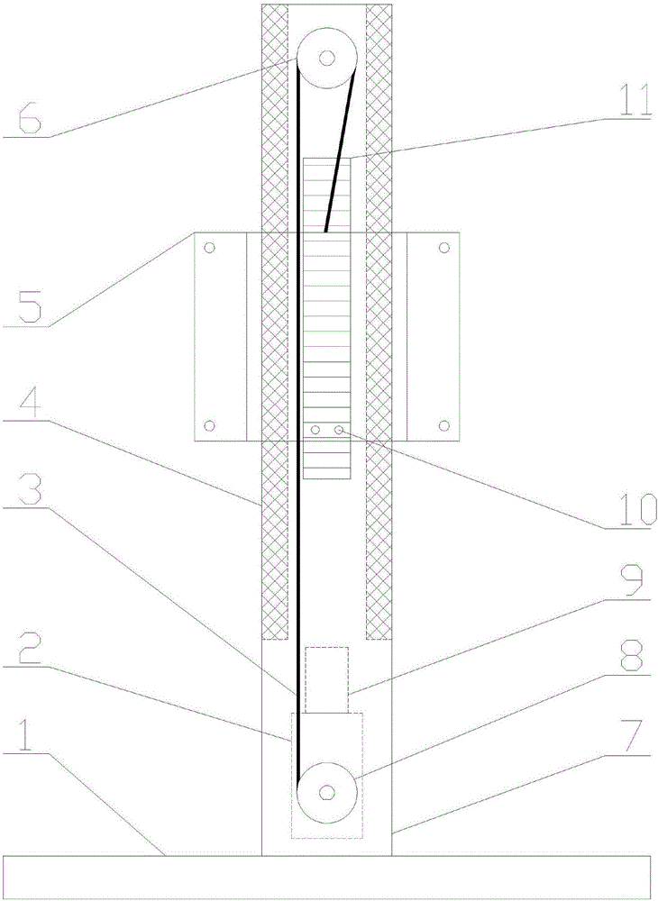
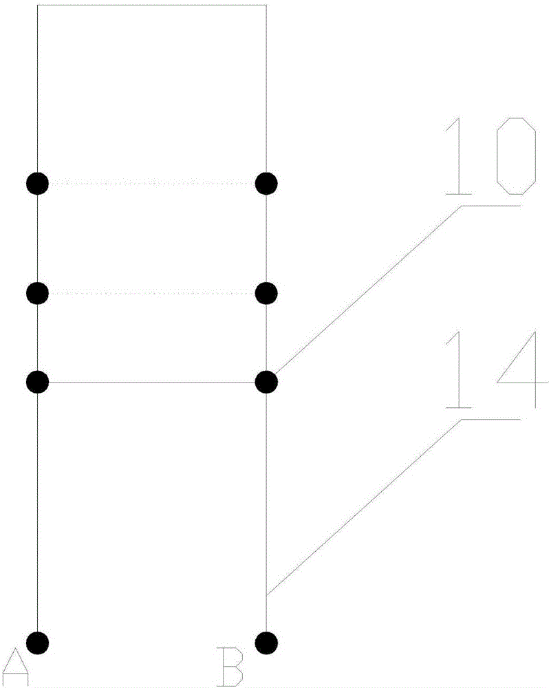
[0045] as attached figure 1 As shown, the automatic lifting computer monitor support of the present invention includes a support part, a lifting device, a control part and a power supply part; the lifting device is arranged in the supporting part, and the control part includes a position detection circuit 11 and a control lifting device lifting The single-chip microcomputer 9; the position detection circuit 11 is connected with the single-chip microcomputer 9; the power supply part is connected with the control part and the lifting device; the position detection circuit 11 includes a U-shaped resistor 14 and two position sensing pins 10, The U-shaped resistor 14 is fixed on the supporting part, the position sensing pin 10 is fixed on the lifting device, and the two position sensing pins 10 are connected and movably connected to both ends of the U-shaped resistor 14 .

[0046] Described lifting device comprises worm gear motor 2, driving wheel 8, stay rope 3, driven wheel 6, sl...

Embodiment 2

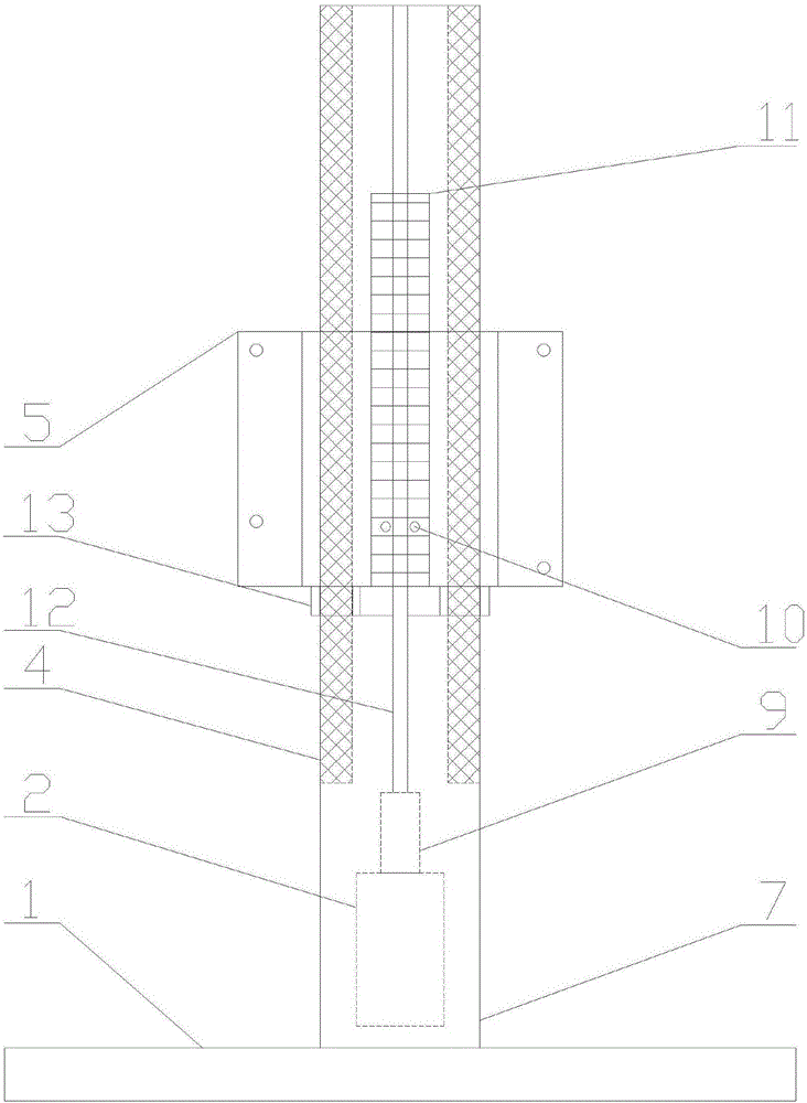
[0065] as attached figure 2 As shown, the lifting device of the present invention is a screw lifting device, and the screw lifting device includes a worm gear motor 2, a threaded screw 12, a guide rail 13 with a threaded hole, a sliding track 4 and a display fixed tackle 5. The screw 12 is fixed on the output rotating shaft of the worm gear motor 2; the screw 12 is matched with the threaded hole of the guide rail 13; the guide rail 13 is movably fixed on the sliding track 4; the display is fixed on the trolley 5 is fixed on the guide rail 13; the single-chip microcomputer 9 is connected to the worm gear motor 2. Only the lifting device of this embodiment is different from that of Embodiment 1, and other structures are the same as those of Embodiment 1 except that.


PUM


Abstract

The invention relates to an automatic-rise-fall computer display device bracket which comprises a support unit, a lifting device, a control unit and a power supply unit, wherein the lifting device is arranged in the support unit; the control unit comprises a position detection circuit and a singlechip for controlling the lifting device to rise and fall; the power supply unit is connected with the control unit and lifting device; the position detection circuit comprises a U-shaped resistor and two position sensing elastic needles; the U-shaped resistor is fixed to the support unit; the position sensing elastic needles are fixed to the lifting device; and the two position sensing elastic needles communicate with each other and are movably connected with both ends of the U-shaped resistor. By adopting the singlechip and position detection circuit to control the rise and fall process, the rise and fall distance can be accurately controlled, and the rise and fall stop time can be accurately controlled; and the rise or fall speed can be accurately changed by changing the transmission ratio of the worm and gear.

Description

technical field [0001] The invention relates to the technical field of automatic control lifting, in particular to an automatic lifting computer monitor support. Background technique [0002] With the popularization of computers, more and more people use computers to work, and problems arise. When people operate computers or use computers to read, they often maintain a posture for a long time, and the viewing angle is generally fixed in one direction. It is easy to cause visual fatigue and other eye diseases; and maintaining a posture for a long time is easy to cause cervical spondylosis, frozen shoulder, etc. According to statistics, more than 90% of white-collar workers suffer from mild or severe cervical spondylosis. The main reason is that they have been in a single fixed posture for a long time. And present conventional monitor is fixed, and this has caused people's line of sight to be fixed at an angle for a long time, therefore, can only maintain a posture when readi...

Claims


Application Information

Patent Timeline
IPC IPC(8): G06F1/16F16M11/04F16M11/24F16M13/00
CPCG06F1/1601F16M11/046F16M11/24F16M13/005
Inventor 叶建新
Owner 叶建新
Why Eureka
Try Eureka