A chip eutectic welding method

A eutectic welding and chip technology, which is applied in welding equipment, manufacturing tools, auxiliary devices, etc., can solve the problem of dislocation between chips and pads, and achieve the effect of solving chip and pad misalignment, low cost, and effective mechanical support

Active Publication Date: 2019-02-26
THE 41ST INST OF CHINA ELECTRONICS TECH GRP
View PDF4 Cites 2 Cited by
  • Summary
  • Abstract
  • Description
  • Claims
  • Application Information

AI Technical Summary

Problems solved by technology

[0005] The invention proposes a chip eutectic welding method, which solves the problem of misalignment between the chip and the gasket during chip eutectic welding

Method used


Image

  • A chip eutectic welding method
  • A chip eutectic welding method
  • A chip eutectic welding method

Examples


Embodiment Construction

[0025] The following will clearly and completely describe the technical solutions in the embodiments of the present invention with reference to the accompanying drawings in the embodiments of the present invention. Obviously, the described embodiments are only some, not all, embodiments of the present invention. Based on the embodiments of the present invention, all other embodiments obtained by persons of ordinary skill in the art without making creative efforts belong to the protection scope of the present invention.

[0026] The purpose of the present invention is to provide a chip eutectic welding method, which can provide positioning for the chip during vacuum eutectic welding of GaAs-based chips, and solve the current problem of dislocation between chips and pads during vacuum eutectic welding of chips.

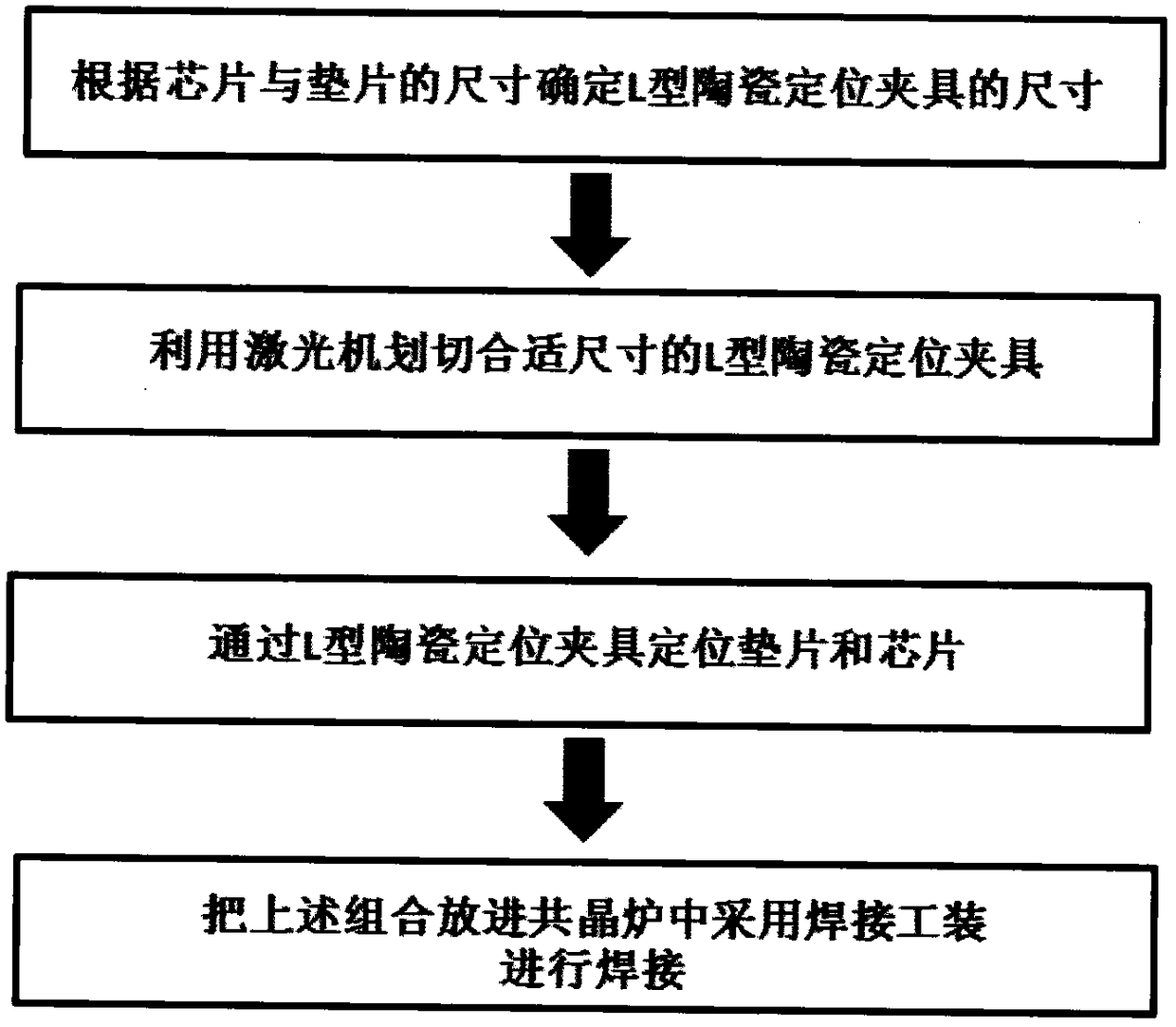
[0027] Therefore, the present invention provides a chip eutectic bonding method, such as figure 1 shown, including the following steps:

[0028] Step (a), determining ...


PUM

PropertyMeasurementUnit
thicknessaaaaaaaaaa
thicknessaaaaaaaaaa
thicknessaaaaaaaaaa

Abstract

The present invention proposes a chip eutectic welding method, comprising the following steps: step (a), determining the size of the L-shaped ceramic positioning fixture according to the size of the gasket; step (b), using a laser machine to cut the corresponding size L-shaped ceramic positioning fixture; step (c), in the process of positioning the chip, first adopt the L-shaped ceramic positioning fixture to fix the gasket, then put the soldering piece on the gasket, and finally put the chip on the soldering piece; step (d) After the chip is fixed by the positioning fixture, put it into the vacuum eutectic furnace and use the welding tool for eutectic welding. In the chip eutectic welding method of the present invention, the L-shaped ceramic positioning fixture is prepared by a laser machine, which effectively solves the problem of misalignment between the chip and the pad during eutectic welding. The method is simple, low in cost, and strong in feasibility; Ceramics are used as the base material, which can provide effective mechanical support and have a wide range of applications.

Description

technical field [0001] The invention relates to the technical field of microwave and millimeter wave micro-assembly, in particular to a chip eutectic welding method. Background technique [0002] Vacuum eutectic welding technology is a kind of welding that uses the characteristics of eutectic alloy to realize the welding of chip and substrate, substrate and shell, cover plate and shell. Since eutectic solder pads have better thermal conductivity and electrical conductivity than conductive adhesives, and with the increase in the power of chip integrated products, more and more chips need to use eutectic soldering instead of conductive adhesive bonding to achieve interconnection. [0003] Vacuum eutectic welding belongs to the method of thermocompression welding. Therefore, in order to obtain the eutectic welding effect of high electrical conductivity, high thermal conductivity and low void rate in GaAs-based chips, it is necessary to provide a certain pressure on the chip dur...

Claims


Application Information

Patent Timeline
Patent Type & Authority Patents(China)
IPC IPC(8): H01L21/50B23K1/008B23K3/08
Inventor 宋志明李红伟莫秀英曹乾涛吴红
Owner THE 41ST INST OF CHINA ELECTRONICS TECH GRP
Why Eureka
Try Eureka