Lens and method for generating vortex beam based on reflecting super-surface

A metasurface, reflective technology, used in electrical components, antennas, etc., can solve problems such as thickness limitations, and achieve the effect of operating frequency bandwidth, efficient generation, and overcoming thickness limitations.

Active Publication Date: 2016-10-12
HARBIN INST OF TECH
View PDF6 Cites 22 Cited by
  • Summary
  • Abstract
  • Description
  • Claims
  • Application Information

AI Technical Summary

Problems solved by technology

[0003] The purpose of the present invention is to solve the problem that the traditional method of generating vortex beams by using a helical phase wav...

Method used


Image

  • Lens and method for generating vortex beam based on reflecting super-surface
  • Lens and method for generating vortex beam based on reflecting super-surface
  • Lens and method for generating vortex beam based on reflecting super-surface

Examples


specific Embodiment approach 1

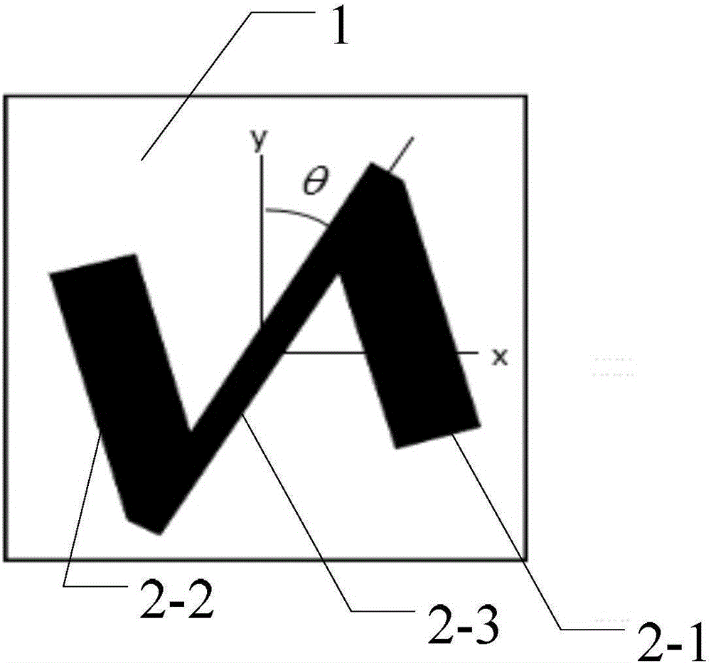
[0021] Specific implementation mode one: combine figure 1 Specifically explain this embodiment, the lens for generating a vortex beam based on a reflective metasurface described in this embodiment includes m×n periodically arranged phase mutation units, and both m and n are positive integers;

[0022] Each phase mutation unit includes a substrate 1 and an inverse Z-shaped metal layer 2 located on the surface of the substrate,

[0023] Inverse Z-shaped metal layer 2 includes metal strip one 2-1, metal strip two 2-2 and inclined strip 2-3, metal strip one 2-1 and metal strip two 2-2 are parallel, and inclined strip 2-3 connects the metal strip One 2-1 and metal strip two 2-2, take one side of the substrate as the x-axis, the side adjacent to this side as the y-axis, and the angle between the center line of the inclined strip 2-3 and the y-axis is θ, where l is the number of orbital angular momentum, The value range of is [0,2π), and x and y are respectively the abscissa an...

specific Embodiment approach 2

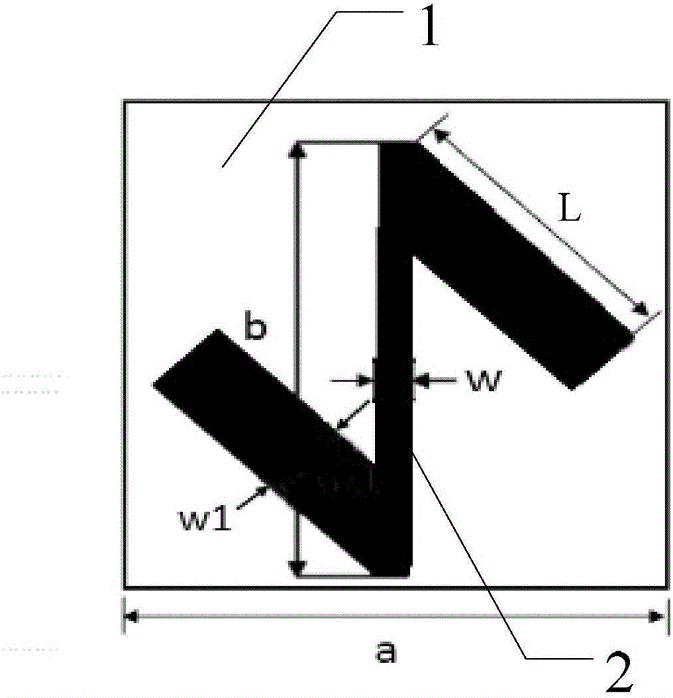
[0029] Specific implementation mode two: combination figure 2 and image 3 Describe this embodiment in detail. This embodiment is a further description of the lens that generates a vortex beam based on a reflective metasurface described in Embodiment 1. In this embodiment, the substrate 1 is a square, and the side length a is 16.2mm. The length L of the first metal strip 2-1 and the second metal strip 2-2 is 9.24mm, and the width w1 is 2.7mm. The length b of the inclined strip 2-3 is 14.88mm, and the width w is 0.54mm. The phase mutation unit The thickness is 3mm.

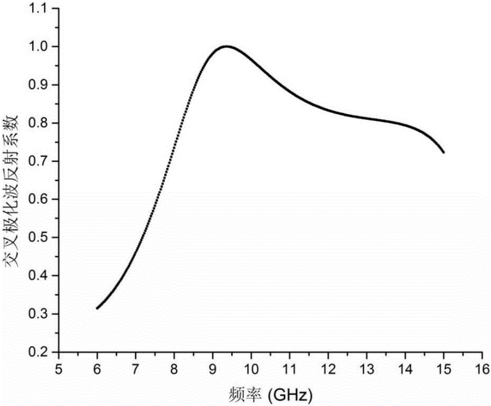
[0030] The thickness of the phase mutation unit is 3mm, which is one-tenth of the wavelength corresponding to the center frequency of 10GHz in the 8GHz-12GHz working bandwidth, which is a sub-wavelength thickness. The phase mutation unit has a band-pass transmission characteristic for circularly polarized electromagnetic waves.

[0031] image 3 It is the cross-polarized wave reflection coefficient graph, it ca...

specific Embodiment approach 3

[0032] Specific implementation mode three: combination Figure 4 and Figure 5 Describe this embodiment in detail. This embodiment is a further description of the lens that generates vortex beams based on the reflective metasurface described in Embodiment 2. In this embodiment, m×n is a rectangular array, along the positive direction of the x-axis In the same period of , the relative rotation angle of adjacent phase mutation units is π / 6, and the counterclockwise direction is positive, and the clockwise direction is negative.

[0033] For a lens with a horizontal phase gradient, such as Figure 4 As shown, there are two components with different handedness in the reflected field, and the propagating direction of the component that maintains the handedness of the incident circularly polarized wave conforms to the traditional reflection law. The included angles formed by the lines are equal; the propagation direction of the component opposite to the incident circularly polariz...


PUM

PropertyMeasurementUnit
Lengthaaaaaaaaaa
Widthaaaaaaaaaa
Length baaaaaaaaaa

Abstract

The invention provides a lens and method for generating a vortex beam based on a reflecting super-surface, relates to a technology for generating the vortex beam based on a phase discontinuous super-surface, and aims at solving the problem that a traditional method for generating the vortex beam by a spiral phase wave plate is limited by the thickness when the wavelength is relatively large. The lens comprises m*n periodically arranged phase change units, wherein each phase change unit comprises a substrate and a reversed Z-shaped metal layer located on the surface of the substrate; each reversed Z-shaped metal layer comprises a metal strip I, a metal strip II and an inclined strip; employing one side of each substrate as an x axis and the side adjacent to the side as a y axis, the included angle between the central line of the corresponding inclined strip and the y axis is theta; the formula is as shown in the specification, wherein l is the orbital angular momentum quantum number; and the formula is as shown in the specification. Incident light, entering the lens, of a circularly polarized wave and abnormally reflected light generated when the circularly polarized wave vertically enters the lens are symmetrical about a normal line; a cross-polarized reflection wave is vertical to reflection of the lens; and the abnormal reflection angle is as shown in the specification. The lens and the method are suitable for generating the vortex beam.

Description

technical field [0001] The invention relates to a technology for generating vortex beams based on phase discontinuous metasurfaces. Background technique [0002] Electromagnetic waves with orbital angular momentum exhibit a spiral wavefront phase distribution when traveling in free space, so they are also called vortex beams. On the cross-section perpendicular to the propagation direction of the vortex beam, the electromagnetic wave has a phase distribution related to the azimuth angle, and the mathematical expression is in, is the phase angle on the section, l is an integer (0, ±1, ±2...), and l is the number of orbital angular momentum. The orbital angular momentum characteristics of electromagnetic waves have far-reaching application prospects. The generation of the traditional vortex wave beam is to use the characteristics of different thicknesses of the helical phase plate at different azimuth angles to realize the phase distribution on the cross-section of the tra...

Claims


Application Information

Patent Timeline
IPC IPC(8): H01Q15/08
CPCH01Q15/08
Inventor 张狂杨海棠丁旭旻吴群
Owner HARBIN INST OF TECH
Why Eureka
Try Eureka