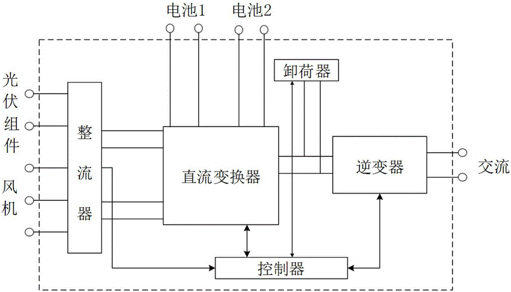
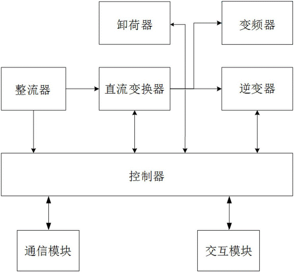
[0025] Such as figure 1 , figure 2 As shown, the power supply access device of an embodiment of the present invention is used to connect the power generation unit and the energy storage unit, and includes a rectifier, a DC converter, an unloader, and an inverter. The rectifier is used for the input of the power generation unit, and the DC The converter is used for boosting, the unloader is used to release excess energy, the inverter is used to convert DC to AC, and the power supply access device also includes a controller for controlling the DC converter, the unloader and the inverter.
[0026] In this embodiment, the DC converter, the unloader, and the inverter share a single controller, which saves the controllers of three circuits, reduces the occupied space and reduces the cost.
[0027] The power generation unit is a DC power generation device and/or AC power generation device, as long as the DC power generation device and AC power generation device within a certain voltage range can be connected, for example, the input voltage range of the DC power generation device is: 60~350V, The input voltage range is: 60~350V.
[0028] The DC power generation device may be a photovoltaic module.
[0029] The AC power generation device can be a fan or a diesel generator.
[0030] The DC converter is realized by the BOOST boost circuit.
[0031] The unloader controls its turn-on and turn-off by controlling the IGBT to release excess energy. IGBT (InsulatedGate Bipolar Transistor, insulated gate bipolar transistor), is a composite fully controlled voltage-driven power semiconductor device composed of BJT (bipolar transistor) and MOS (insulated gate field effect transistor), and MOSFET The advantages of high input impedance and low on-voltage drop of GTR.
[0032] The inverter is realized by a DC-AC inverter circuit.
[0033] The inverter can output standard AC power: 220VAC, 50Hz AC, which can drive various household appliances that meet this voltage standard and whose power is less than 5KW, including washing machines, refrigerators, rice cookers, televisions, computers, etc. Household appliances.
[0034] In this embodiment, the power generation unit is a photovoltaic module and a fan, and the input of the power supply access device is low-voltage direct current from photovoltaic and three-phase alternating current from the fan. After rectification, it is boosted by the BOOST circuit and output to the high-voltage DC bus. Provide DC support for the inverter; at the same time, the power supply access device can also be connected to one or more lead-acid batteries, lead-carbon batteries or lithium batteries, or other batteries of the same voltage level, which are boosted by the BOOST circuit for the inverter The power supply device provides a supplement to make the power supply system constituted by the power supply access device stable and reliable power supply.
[0035] Of course, in another embodiment, an energy storage unit, such as a lead-acid battery, can also be connected in parallel to the high-voltage bus, which is not limited in the present invention.
[0036] The rectifier is an uncontrolled rectifier or a controllable rectifier.
[0037] Uncontrolled rectifier circuit is a rectifier circuit composed of rectifier diodes with no control function. When the input AC voltage is constant, the DC voltage obtained is a circuit that cannot be adjusted. It is divided into single-phase and three-phase uncontrolled rectifier circuits.
[0038] In this embodiment, single-phase and three-phase uncontrolled rectifier circuits are used. The single-phase uncontrolled rectifier circuit is used for rectification of photovoltaic module input, and the three-phase uncontrolled rectifier circuit is used for rectification of fan input. The controller only collects data. The rectifier circuit is not controlled.
[0039] The controllable rectifier is a rectifier circuit composed of controllable rectifier diodes. When the input AC voltage is constant, the DC voltage obtained is a circuit that can be adjusted. It is divided into single-phase and three-phase controllable rectifier circuits. There are more three-phase controllable rectifier circuits. , There are fewer single-phase controllable rectifier circuits.
[0040] In another embodiment, a controllable rectifier is used, a single-phase controllable rectifier circuit is used to rectify the input of photovoltaic modules, a three-phase controllable rectifier circuit is used to rectify the input of a fan, and the controller uses a controllable rectifier diode to control the rectification The circuit controls and regulates the voltage on the high-voltage bus.
[0041] The energy storage unit is a lead-acid battery, a lead-carbon battery or a lithium battery. In this embodiment, the energy storage unit is two lead-acid batteries, which can prolong the service life of the battery and increase the economy of the battery; or when the load power is large, two batteries can be used for discharge at the same time. Of course, there can also be one energy storage unit, which is not limited in the present invention.
[0042] Multiple or all of the rectifier, DC converter, unloader and inverter are arranged on the same PCB board, even all modules are arranged on the same PCB board, and directly connected on the PCB board, reducing the need for external wiring The cable connection improves the connection reliability of the power supply access device, thereby ensuring the reliable power supply of the power supply system formed by the power supply access device.
[0043] The power supply access device also includes a communication module for transmitting data of the power supply access device to the remote receiving end.
[0044] The power supply access device also includes an interactive module for operator interactive operations, such as a touch screen, to facilitate operator interactive operations.
[0045] The power supply access device also includes a frequency converter for outputting three-phase alternating current.
[0046] The battery management system (BMS) is mainly to improve the utilization rate of the battery, prevent the battery from being overcharged and over-discharged, extend the service life of the battery, and monitor the state of the battery.
[0047] In this embodiment, the controller can implement the following BMS functions:
[0048] (1) Estimate the State of Charge (SOC) of the energy storage unit, that is, the remaining power of the energy storage unit, to ensure that the SOC is maintained within a reasonable range, thereby preventing the energy storage unit from being overcharged or overdischarged Cause damage;
[0049] (2) During the charge and discharge process of the energy storage unit, the terminal voltage and charge and discharge current are collected in real time to prevent the battery from overcharging or overdischarging.
[0050] In this embodiment, the controller can realize the function of the BMS of the battery, which can effectively save the battery life by 3%, thereby reducing the overall equipment cost.
[0051] The preferred embodiments of the present invention are described in detail above. It should be understood that those of ordinary skill in the art can make many modifications and changes according to the concept of the present invention without creative work. Therefore, all technical solutions that can be obtained by those skilled in the art through logical analysis, reasoning or limited experiments based on the concept of the present invention on the basis of the prior art should fall within the protection scope determined by the claims.