
Sine wave inverter system based on third harmonic eliminating circuit

A technology for eliminating circuits and inverter systems, applied in the field of inverter systems, can solve the problems of low conversion efficiency of inverter systems, achieve the effects of eliminating third harmonics, reducing capacitive current, and reducing energy consumption

Inactive Publication Date: 2016-10-12
CHENGDU SIBOTE TECH CO LTD
View PDF0 Cites 0 Cited by
  • Summary
  • Abstract
  • Description
  • Claims
  • Application Information

AI Technical Summary

Problems solved by technology

[0003] The purpose of the present invention is to solve the defect of low conversion efficiency of the current inverter system and provide a sine wave inverter system based on the third harmonic elimination circuit

Method used


Image

  • Sine wave inverter system based on third harmonic eliminating circuit
  • Sine wave inverter system based on third harmonic eliminating circuit

Examples


Embodiment

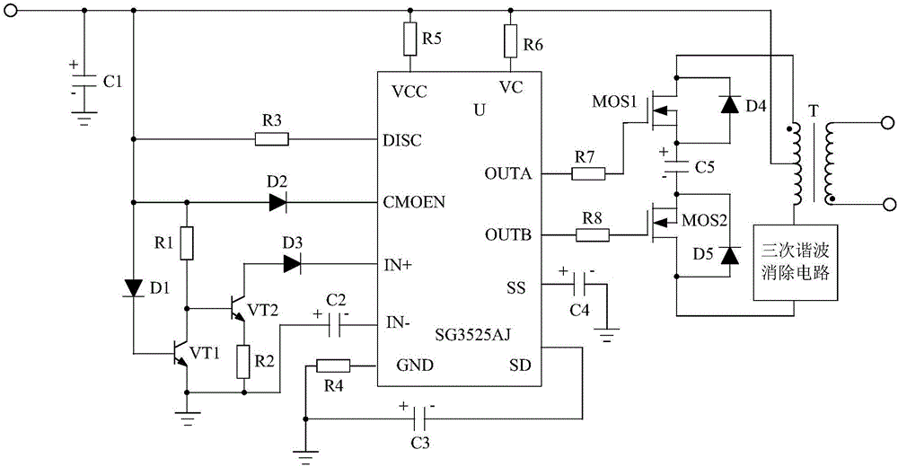
[0016] Such as figure 1 As shown, the present invention mainly consists of a processing chip U, a transformer T, a capacitor C1 with the positive pole as the input terminal and the negative pole grounded, and a resistor R5 connected in series between the positive pole of the capacitor C1 and the VCC pin of the processing chip U, and connected in series with the capacitor The resistor R6 between the positive pole of C1 and the VC pin of the processing chip U, the positive pole is connected to the SS pin of the processing chip U, the capacitor C4 with the negative pole grounded, the negative pole is connected with the SD pin of the processing chip U, and the positive pole is grounded Capacitor C3, a resistor R4 connected in series between the positive pole of capacitor C3 and the GND pin of the processing chip U, a pulse width modulation circuit connected in series between the positive pole of capacitor C1 and the processing chip U, connected to the processing chip U It consists...


PUM


Abstract

The invention discloses a sine wave inverter system based on the third harmonic elimination circuit, which is characterized in that: a processing chip U, a transformer T, a capacitor C1 whose positive pole is used as an input terminal, and a negative pole grounded is mainly connected to the positive pole of the capacitor C1 in series. It is composed of a resistor R5 between the VCC pin of the processing chip U and the like. The invention adopts the SG3525AJ integrated chip as the processing chip, and uses the pulse width modulation method to control the system, which greatly reduces the energy consumption of the system itself, so that the conversion efficiency of the invention can reach more than 94%. At the same time, the present invention can eliminate the third harmonic in the output current, thereby reducing the capacitive current flowing into the electric load and protecting the electric load from being damaged.

Description

technical field [0001] The invention relates to an inverter system, in particular to a sine wave inverter system based on a third harmonic elimination circuit. Background technique [0002] The inverter system can convert direct current into alternating current, and it is widely used in air conditioners, home theaters, electric tools and other fields. However, the power consumption of the currently used inverter system itself is large, resulting in low conversion efficiency, which cannot meet people's requirements. Contents of the invention [0003] The purpose of the present invention is to solve the defect of low conversion efficiency of the current inverter system, and provide a sine wave inverter system based on a third harmonic elimination circuit. [0004] The purpose of the present invention is achieved through the following technical solutions: a sine wave inverter system based on a third harmonic elimination circuit, mainly composed of a processing chip U, a tran...

Claims


Application Information

Patent Timeline
Patent Type & Authority Applications(China)
IPC IPC(8): H02M7/537H02M1/12
CPCH02M7/537H02M1/12
Inventor 不公告发明人
Owner CHENGDU SIBOTE TECH CO LTD
Learn More