
Power driver

A technology for electrical appliances and driving circuit boards, which is used in electrical components, AC motor control, estimation/correction of motor parameters, etc. The effect of avoiding voltage fluctuation and reducing loop loss

Inactive Publication Date: 2016-10-12
哈尔滨泾铎技术有限公司
View PDF12 Cites 1 Cited by
  • Summary
  • Abstract
  • Description
  • Claims
  • Application Information

AI Technical Summary

Problems solved by technology

[0006] An object of the present invention is to provide a driver, which is used to solve the problems in the prior art that cannot adapt to special working conditions such as soft start and jog of the motor

Method used


Image

  • Power driver
  • Power driver
  • Power driver

Examples


specific Embodiment approach 1

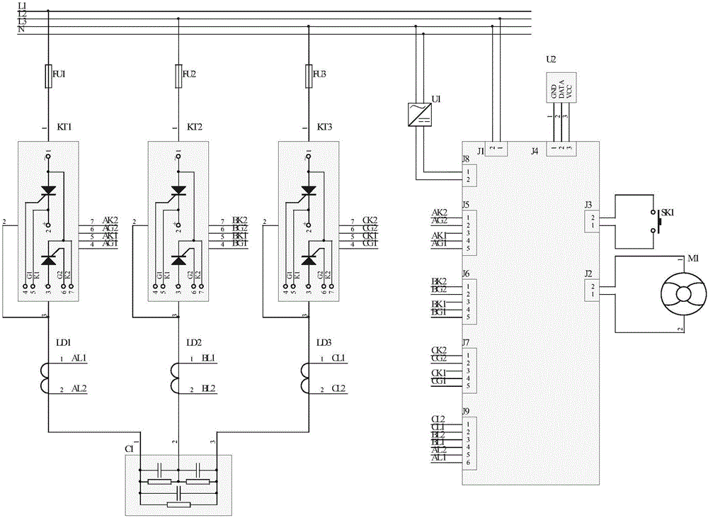
[0035] Specific implementation mode one: the driving device of this implementation mode is as follows figure 2 As shown, where L1, L2, L3, and N are the four lead wires of the motor. The power input terminal J8 of the drive circuit board is connected to the lead wires L3 and L2 of the motor through the switching power supply U1, the power detection terminal J1 detects the voltage, the timing terminal J4 is connected to the timing chip U2, the power reset terminal J3 is connected to the reset button SK1, and the fan is controlled. Terminal J2 is connected with fan motor M1. The drive circuit board also has A-phase thyristor control terminal J5, B-phase thyristor control terminal J6, and C-phase thyristor control terminal J7, and their pins are connected to A-phase thyristor switch KT1 as shown in the figure. , the corresponding pins of the B-phase thyristor switch KT2 and the C-phase thyristor switch KT3. One end of the three thyristor switches KT1, KT2, KT3 are respectively...

specific Embodiment approach 2

[0039] Embodiment 2: The difference between this embodiment and Embodiment 1 is that the driving circuit board also includes a differential amplifier, and the input end of the differential amplifier is the current transformer end, which is used to amplify the detected current for easy detection. The circuit diagram of the differential amplifier is shown in Figure 5 shown.

[0040] Other components and parameters are the same as those in the first embodiment.

specific Embodiment approach 3

[0041] Embodiment 3: The difference between this embodiment and Embodiment 1 or 2 is that the drive circuit board also includes a reset terminal, which is connected to a reset button. When the drive circuit board fails, the reset operation can be performed through the reset button.

[0042] Other components and parameters are the same as those in Embodiment 1 or Embodiment 2.


PUM


Abstract

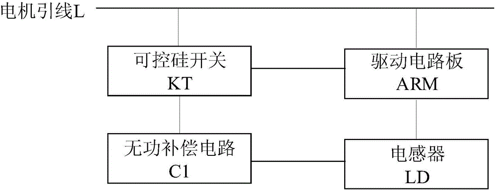
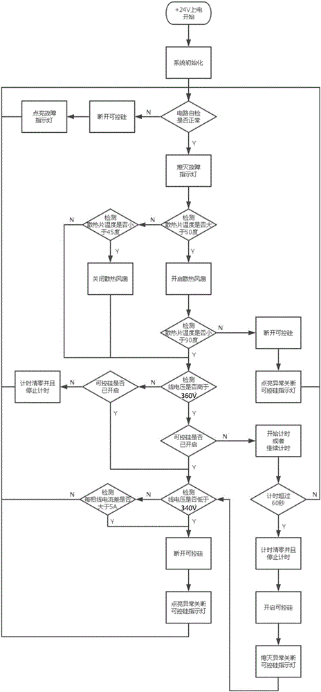
The invention discloses a driving device, which includes a driving circuit board and a peripheral circuit. One terminal is connected to the lead wire of the motor, and the second terminal is connected to the reactive power compensation circuit; the drive circuit board has a voltage detection terminal, a current detection terminal and a thyristor control terminal, the voltage detection terminal is connected to the motor lead wire to detect voltage, and the current detection terminal is connected to the inductance The inductor is connected, the inductor and the reactive power compensation circuit have mutual inductance to detect the current, and the driving circuit board controls the thyristor switch to open or close according to the detected voltage and the detected current. The present invention performs current compensation on motors, reduces apparent power and unit power consumption, and can be directly applied to motors adopting soft start mode and direct start mode without adding other additional equipment.

Description

technical field [0001] The invention relates to the field of power compensation equipment, and more specifically, to a driver. Background technique [0002] AC asynchronous motors have been widely used in industry, agriculture and other fields due to their simple structure and low price. At present, the annual power consumption of AC asynchronous motors in my country accounts for more than 80% of industrial power consumption. [0003] AC asynchronous motor is a multi-parameter, strongly coupled and severely nonlinear controlled object. Its accurate mathematical model is difficult to obtain, and it is also affected by factors such as operating temperature and aging. Therefore, in actual work, most AC asynchronous motors The load is often in a changing state. The design of AC asynchronous motors is based on the principle of optimal efficiency under rated conditions, but uneconomical operation under light load or no-load conditions will result in a large amount of waste of el...

Claims


Application Information

Patent Timeline
Patent Type & Authority Applications(China)
IPC IPC(8): H02P23/00H02P23/14
CPCH02P23/14
Inventor 安洪刚
Owner 哈尔滨泾铎技术有限公司
Learn More