Novel speed regulating apparatus for 3 phase high voltage switch reluctance motor

A high-power switching, reluctance motor technology, applied in the direction of speed/torque control of a single motor, can solve the problems of high insulation level requirements of power units, large number of three-phase transformer secondary groups, signal transmission and testing difficulties, etc. Achieve the effect of low insulation requirements, simple and convenient debugging, and power reduction

Inactive Publication Date: 2011-05-18
NIDEC BEIJING DRIVE TECH CO LTD
View PDF4 Cites 0 Cited by
  • Summary
  • Abstract
  • Description
  • Claims
  • Application Information

AI Technical Summary

Problems solved by technology

[0008] The above-mentioned high-voltage and high-power 3-phase switched reluctance motor speed control device in the direct series mode uses a large number of power units, a large number of power switches, diodes and other components, and a large number of secondary side groups of the three-phase transformer.
In addition to these shortcomings, the voltage of the power unit is high, so the requirements for the insulation level of the power unit are high, and it also brings certain difficulties in signal transmission and testing.

Method used


Image

  • Novel speed regulating apparatus for 3 phase high voltage switch reluctance motor
  • Novel speed regulating apparatus for 3 phase high voltage switch reluctance motor
  • Novel speed regulating apparatus for 3 phase high voltage switch reluctance motor

Examples


Embodiment Construction

[0027] In order to make the object, technical solution and advantages of the present invention clearer, the implementation manner of the present invention will be further described in detail below in conjunction with the accompanying drawings.

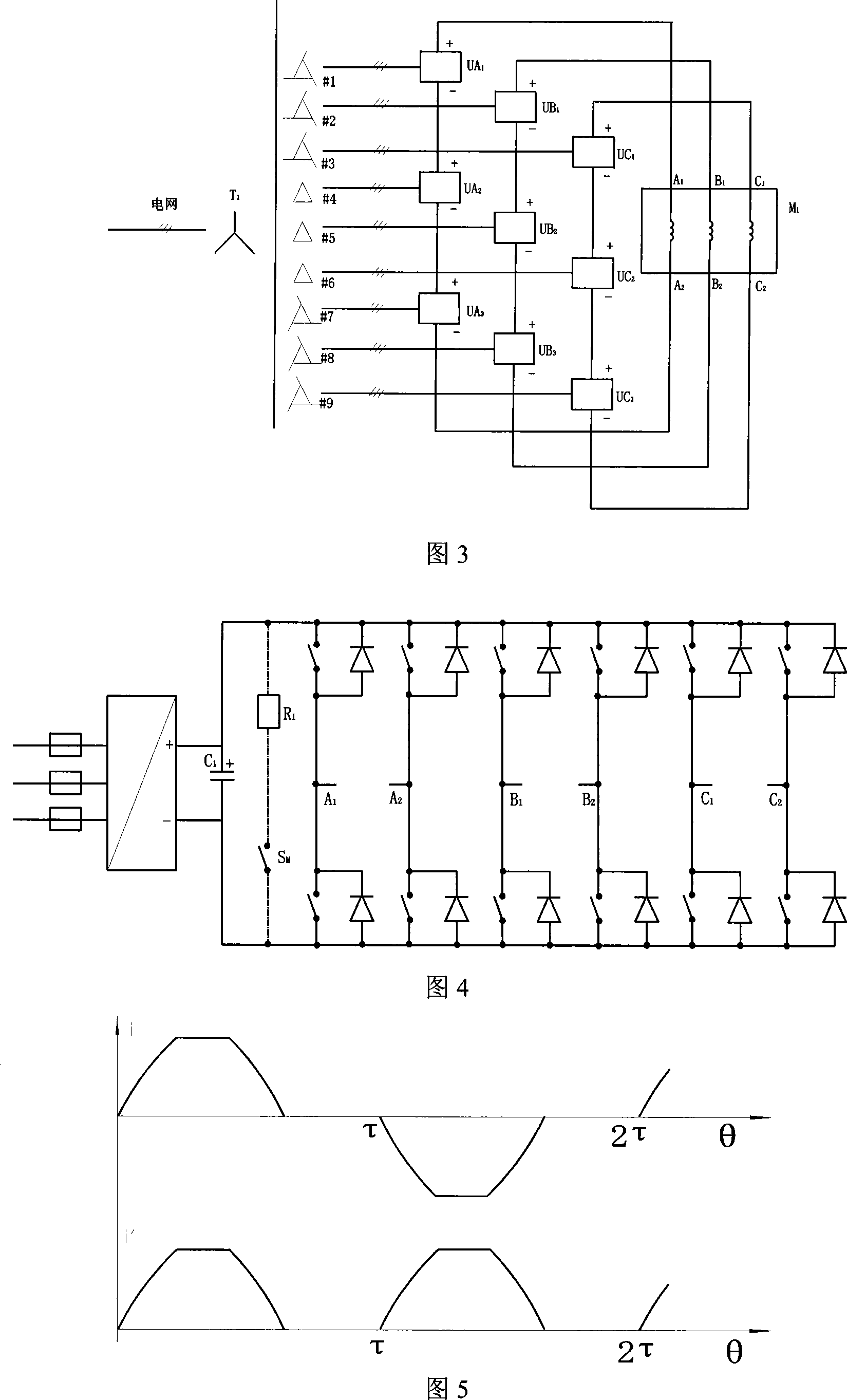
[0028] Fig. 4 shows the circuit diagram of the common type power unit of the present invention. The three-phase bridge rectification adopts capacitor filtering, and its three-phase input is connected with a fuse for protection, and sometimes it can be used as an isolating switch. The power inverter circuit has a total of six push-pull bridge arms, which constitute three independent single-phase full-bridge inverter circuits. As the two pairs of power switches on the diagonal are turned on in turn on average, the output drive current is positive and negative alternately. . The dotted line shows the voltage-limiting discharge circuit, which should be set when necessary.

[0029] In the power unit of the present invention, the power inve...


PUM


Abstract

The invention provides a novel speed regulation device used for a three-phase high-voltage large-power switch reluctance motor, belonging to the field of the speed regulation of the motor. The speed regulation device comprises a three-phase phase-shifting transformer, a high-voltage large-power switch reluctance motor, Z power units and 3Z single-phase isolation transformers, wherein, Z is more than or equal to 2; the three-phase phase-shifting transformer is connected with the input terminals of Z power units; the output of the Z power units passes by 3Z single-phase isolation transformers and then are connected with Z speed regulation devices of the three-phase high-voltage large-power switch reluctance motor in series, thus driving the high-voltage large-power switch reluctance motor. Compared with the speed regulation device of the motor of a direct serial connection type, the power units are reduced by three times, the power elements are reduced correspondingly, the auxiliary windings of the three-phase phase-shifting transformer are reduced by three times, the structure is greatly simplified, and the apparatus power is reduced; and all power units work at normal voltage and have low insulation requirement, the debugging operation is simple and convenient, and the operation is reliable and easy to be realized.

Description

technical field [0001] The invention relates to a motor speed regulating device, in particular to a three-phase high-voltage high-power switched reluctance motor speed regulating device. Background technique [0002] The 3-phase switched reluctance motor has been widely used. After omitting the power-on current limiting circuit, the main circuit of the general 3-phase switched reluctance motor speed control device is shown in Figure 1. The motor has three self-isolated phase windings. Driven by three single-phase half-bridge power inverter circuits respectively, the conduction angle is (1 / 3~1 / 2) times the rotor pole pitch. [0003] The entire inverter circuit is powered by a three-phase bridge rectifier power supply, and the power supply is filtered by a capacitor. If necessary, a limited-voltage discharge circuit is connected in parallel with the capacitor, and the circuit is composed of a power switch and a resistor in series. If the speed regulating device is a feedback...

Claims


Application Information

Patent Timeline
Patent Type & Authority Patents(China)
IPC IPC(8): H02P6/08
Inventor 裘锦灼
Owner NIDEC BEIJING DRIVE TECH CO LTD
Why Eureka
Try Eureka