Limiting number of retransmission attempts for data transfer via network interface controller

a network interface controller and retransmission limit technology, applied in data switching networks, instruments, coding, etc., can solve the problems of large burden on 2 ghz cpu, common 1 gbps network connection, large communication bandwidth, etc., to reduce memory bandwidth, efficient recovery, and reduce latency.

Active Publication Date: 2005-06-16
MELLANOX TECHNOLOGIES LTD
View PDF6 Cites 72 Cited by
  • Summary
  • Abstract
  • Description
  • Claims
  • Application Information

AI Technical Summary

Benefits of technology

[0030] The invention includes an RNIC implementation that performs direct data placement to memory where all received DDP segments of a particular connection are aligned, or moves data through reassembly buffers where some DDP segments of a particular connection are non-aligned. The type of connection that cuts-through without accessing the reassembly buffers is referred to as a “Fast” connection, while the other type is referred to as a “Slow” connection. When a consumer establishes a connection, it specifies a connection type. For example, a connection that would go through the Internet to another continent has a low probability to arrive at a destination with aligned segments, and therefore should be specified by a consumer as a “Slow” connection type. On the other hand, a connection that connects two servers in a storage area network (SAN) has a very high probability to have all DDP segments aligned, and therefore would be specified

Problems solved by technology

The communications bandwidth increase, however, is now beginning to outpace the rate at which central processing units (CPUs) can process data efficiently, resulting in a bottleneck at server processors, e.g., RNIC 4.
For example, a common 1 Gbps network connection, if fully utilized, can be a large burden to a 2 GHz CPU.
In addition, this approach presents a very compact and powerful solution with low cost.
Unfortunately, since the TCP/IP stack was defined and developed for implementation in software, generating a TCP/IP stack in hardware has resulted in a wide range of new problems.
For example, problems that arise include: how to implement a software-based protocol in hardware FSMs and achieve improved performance, how to design an advantageous and efficient interface to upper layer protocols (ULPs) (e.g., application protocols) to provide a faster implementation of the ULP, and how to avoid new bottle-necks in a scaled-up implementation.
Unfortunately, protocols placed over a TCP/IP stack typically require many copy operations because the ULP must supply buffers for indirect data placement, which adds latency an

Method used


Image

  • Limiting number of retransmission attempts for data transfer via network interface controller
  • Limiting number of retransmission attempts for data transfer via network interface controller
  • Limiting number of retransmission attempts for data transfer via network interface controller

Examples


Embodiment Construction

[0057] The following outline is provided for organizational purposes only: I. Overview, II. InLogic, III. OutLogic, and IV. Conclusion.

I. Overview

[0058] A. Environment

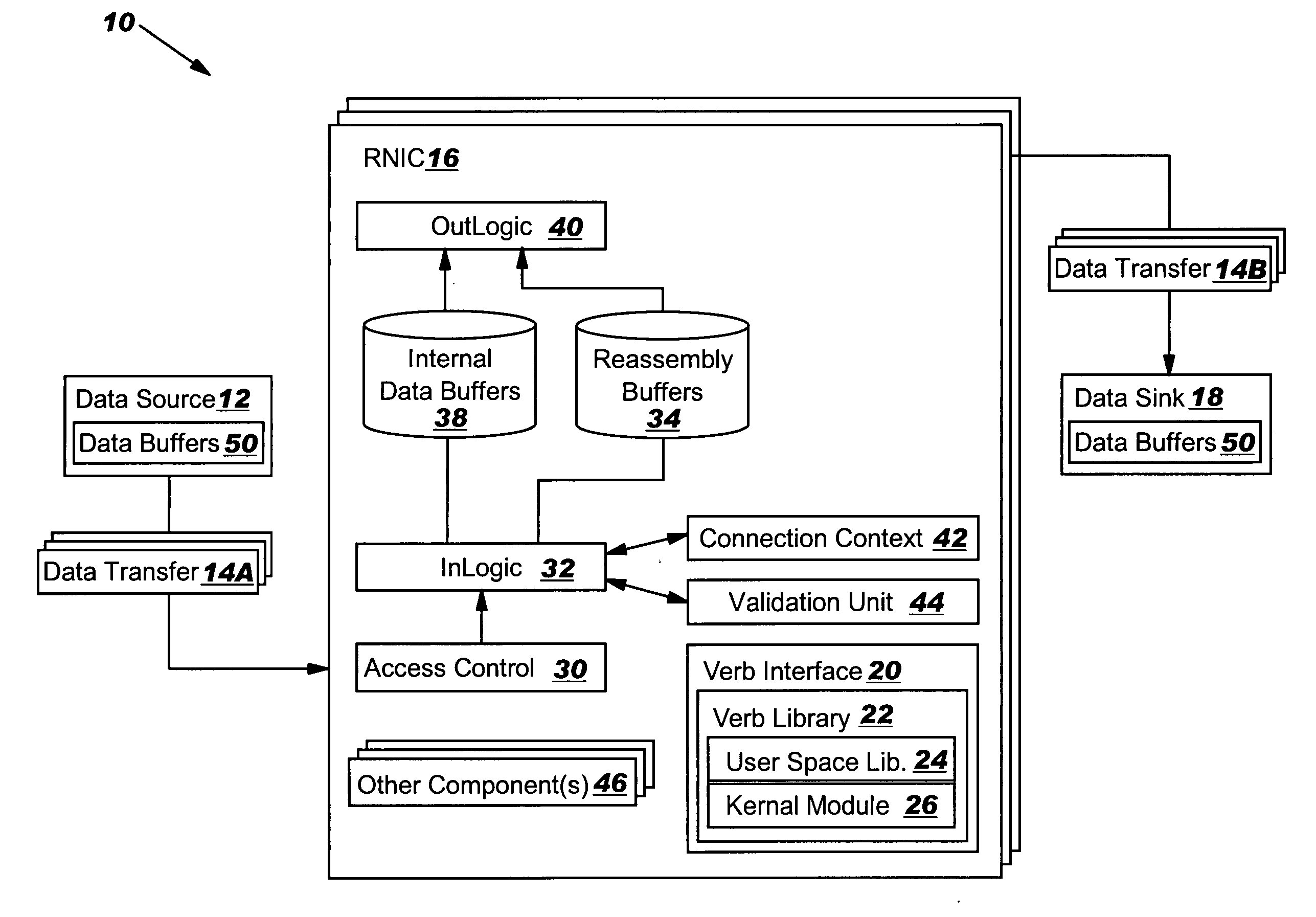
[0059] With reference to the accompanying drawings, FIG. 2A is a block diagram of data transfer environment 10 according to one embodiment of the invention. Data transfer environment 10 includes a data source 12 (i.e., a peer) that transmits a data transfer 14A via one or more remote memory data access (RDMA) enabled network interface controller(s) (RNIC) 16 to a data sink 18 (i.e., a peer) that receives data transfer 14B. For purposes of description, an entity that initiates a data transfer will be referred to herein as a “requester” and one that responds to the data transfer will be referred to herein as a “responder.” Similarly, an entity that transmits data shall be referred to herein as a “transmitter,” and one that receives a data transfer will be referred to herein as a “receiver.” It should be recognized th...


PUM


Abstract

An RNIC implementation that performs direct data placement to memory where all segments of a particular connection are aligned, or moves data through reassembly buffers where all segments of a particular connection are non-aligned. The type of connection that cuts-through without accessing the reassembly buffers is referred to as a “Fast” connection because it is highly likely to be aligned, while the other type is referred to as a “Slow” connection. When a consumer establishes a connection, it specifies a connection type. The connection type can change from Fast to Slow and back. The invention reduces memory bandwidth, latency, error recovery using TCP retransmit and provides for a “graceful recovery” from an empty receive queue. The implementation also may conduct CRC validation for a majority of inbound DDP segments in the Fast connection before sending a TCP acknowledgement (Ack) confirming segment reception.

Description

BACKGROUND OF THE INVENTION [0001] 1. Technical Field [0002] The present invention relates generally to data transfer, and more particularly, to an RDMA enabled network interface controller (RNIC) with a cut-through implementation for aligned DDP segments. [0003] 2. Related Art [0004] 1. Overview [0005] Referring to FIG. 1A, a block diagram of a conventional data transfer environment 1 is shown. Data transfer environment 1 includes a data source 2 (i.e., a peer) that transmits a data transfer 3A via one or more remote memory data access (RDMA) enabled network interface controller(s) (RNIC) 4 to a data sink 5 (i.e., a peer) that receives data transfer 3B. RNIC 4 includes, inter alia (explained further below), reassembly buffers 6. Networking communication speeds have significantly increased recently from 10 mega bits per second (Mbps) through 100 Mbps to 1 giga bits per second (Gbps), and are now approaching speeds in the range of 10 Gbps. The communications bandwidth increase, howev...

Claims


Application Information

Patent Timeline
IPC IPC(8): H04L1/00H04L1/16H04L1/18H04L12/56
CPCH04L1/0061H04L1/08H04L47/32H04L1/1835H04L47/10H04L1/16H04L47/43
Inventor MACHULSKY, ZORIKMAKHERVAKS, VADIM
Owner MELLANOX TECHNOLOGIES LTD
Why Eureka
Try Eureka