Current compensation method of optical module and optical module

A current compensation, optical module technology, applied in the field of optical transmission, can solve the problem of inaccurate compensation current, and achieve the effect of stable optical power and high accuracy

Active Publication Date: 2018-09-07
HISENSE BROADBAND MULTIMEDIA TECH
View PDF8 Cites 0 Cited by
  • Summary
  • Abstract
  • Description
  • Claims
  • Application Information

AI Technical Summary

Problems solved by technology

[0006] The present invention provides a current compensation method of an optical module and an optical module, which are used to solve the problem of inaccurate compensation current calculated in the prior art

Method used


Image

  • Current compensation method of optical module and optical module
  • Current compensation method of optical module and optical module
  • Current compensation method of optical module and optical module

Examples


Embodiment approach

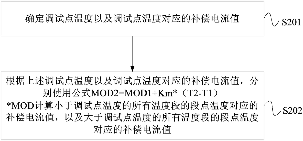
[0043] On the basis of the above-mentioned embodiments, this embodiment involves using the formula MOD2=MOD1+Km*(T2-T1)*MOD to calculate the compensation current value corresponding to the segment point temperature of all temperature segments less than the temperature of the debugging point, and the compensation current value greater than the temperature of the debugging point A specific method for the compensation current value corresponding to the segment point temperature of all temperature segments of the point temperature, that is, Figure 4 The schematic flow chart of the third embodiment of the current compensation method for the optical module provided by the embodiment of the present invention, as shown in Figure 4 As shown, an implementation manner of the above step S202 is:

[0044] S301. Taking the temperature of the debugging point as T1, taking the compensation current value corresponding to the temperature of the debugging point as MOD1, using the formula MOD2=...


PUM


Abstract

The present invention provides a current compensation method for an optical module and the optical module. The method includes: obtaining the current temperature of the optical module; according to the current temperature, searching for a compensation value corresponding to the current temperature in a preset compensation current table. Current value, wherein, the compensation ammeter is used to record the compensation current value corresponding to the segment point temperature of each temperature segment, and the compensation current value corresponding to the segment point temperature of each temperature segment is passed through the formula MOD2=MOD1+Km×( T2-T1)×MOD is calculated and obtained; performing current compensation on the optical module according to the compensation current value corresponding to the current temperature. The compensation current value calculated by the method is closer to the ideal value, and the accuracy of the current compensation is higher, thereby ensuring that the optical power output by the optical module remains stable when the temperature changes.

Description

technical field [0001] The invention relates to optical transmission technology, in particular to a current compensation method of an optical module and the optical module. Background technique [0002] With the development of the optical communication field, the optical module has become an indispensable device in the optical transmission equipment. The optical module converts the electrical signal into an optical signal through the internal optical transmission module and sends it into the optical fiber for transmission. Specifically, in the light emitting module, the driver chip outputs modulation current and bias current to the laser, and the laser emits an optical signal when the current value output to the laser exceeds a threshold current. Lasers are semiconductor devices, and the higher the temperature of the laser, the greater its threshold current. In order to ensure the stability of the optical power of the optical signal output by the laser, when the temperatur...

Claims


Application Information

Patent Timeline
Patent Type & Authority Patents(China)
IPC IPC(8): H04B10/564
CPCH04B10/564
Inventor 鄂文晶林青合李刚
Owner HISENSE BROADBAND MULTIMEDIA TECH
Why Eureka
Try Eureka