Camera base, camera and terminal
A camera and terminal technology, which is applied in image communication, TV, color TV parts, etc., can solve the problems of unfavorable camera installation and layout, large camera thickness and reduced product reliability, etc., so that it is not easy to break and easy to install and arrange , Improve the effect of structural strength
- Summary
- Abstract
- Description
- Claims
- Application Information
AI Technical Summary
Problems solved by technology
Method used
Image
Examples
Embodiment 1
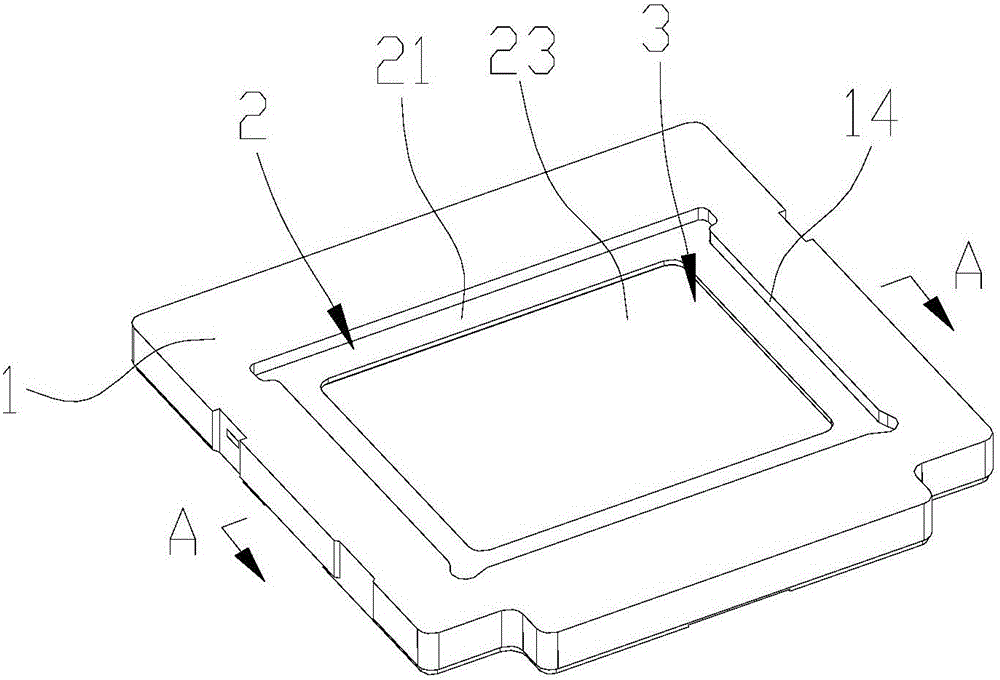
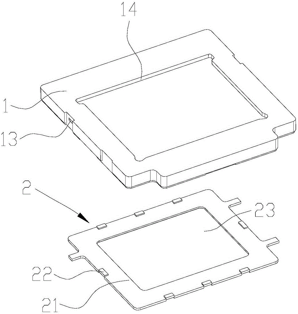
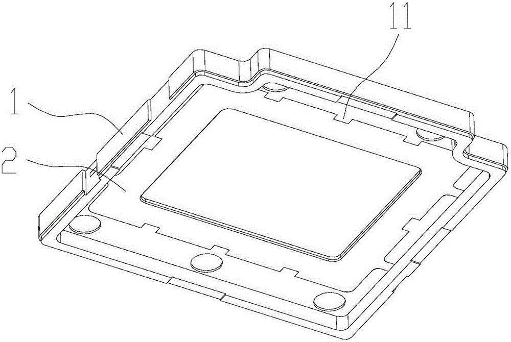
[0020] refer to Figure 1 to Figure 4 , a camera base, including a base body 1 and a metal bracket 2, the metal bracket 2 includes a central bearing part 21 and a first joint part 22 at the edge, and the bearing part 21 is used to carry the optical filter of the camera; The carrying part 21 is provided with a light-transmitting part 23, and the light-transmitting part 23 is used for light filtering of the filter; the seat body 1 includes a second joint part 11, and the second joint part 11 is connected to the The first combining portion 22 is combined and fixed to realize the combination and fixation of the seat body 1 and the metal bracket 2 . Wherein, the metal bracket 2 can be a stainless steel bracket, a copper bracket, an aluminum alloy bracket, etc.; the seat body 1 can be a plastic seat body, etc.; the light-transmitting portion 23 can be a light-transmitting hole.
[0021] As a preferred implementation of this embodiment, the first joint part 22 is injection-molded on...
Embodiment 2
[0029] refer to Figure 8 , a camera, comprising the above-mentioned camera base 4, the carrying portion 21 of the camera base 4 is provided with a filter 5, the top of the filter 5 is provided with a camera module 6, the filter A circuit board 7 is arranged below the sheet 5 , and a lighting chip 8 is arranged on the circuit board 7 , and the lighting chip 8 is arranged at a position corresponding to the light transmission portion 23 of the camera base 4 corresponding to the circuit board 7 . Wherein, the light-transmitting portion 23 may be a light-transmitting hole. During use, external light enters the camera module 6 and is filtered by the optical filter 5 . The filtered light needs to pass through the light hole to reach the lighting chip 8 and be collected by the lighting chip 8 .
[0030]The camera provided by the embodiment of the present invention applies the above-mentioned camera base 4 . In the camera base 4, through the introduction of the metal bracket 2, the ...
Embodiment 3
[0033] A terminal includes the above-mentioned camera. Wherein, the terminal may include at least one of a mobile phone, a navigator, a tablet computer, a camera, a laptop computer, and a smart wearable device.
[0034] The terminal in the embodiment of the present invention uses the above-mentioned camera, and the camera includes a camera base 4 . In the camera base 4, through the introduction of the metal bracket 2, the structural strength of the camera base 4 is effectively improved, so that the camera base 4 is not prone to problems such as cracking; The thickness of the base 4. Moreover, since the metal bracket 2 has a bearing part 21, that is, the camera base 4 of the embodiment of the present invention has a metal bearing part with stronger structural strength, it can form a more stable bearing protection for the optical filter 5, so that the optical filter 5 does not Problems such as breakage are prone to occur; similarly, on the premise of satisfying the structural ...
PUM
| Property | Measurement | Unit |
|---|---|---|
| Thickness | aaaaa | aaaaa |
| Thickness | aaaaa | aaaaa |
Abstract
Description
Claims
Application Information
 - R&D
- Intellectual Property
- Life Sciences
- Materials
- Tech Scout
- Unparalleled Data Quality
- Higher Quality Content
- 60% Fewer Hallucinations
Browse by: Latest US Patents, China's latest patents, Technical Efficacy Thesaurus, Application Domain, Technology Topic, Popular Technical Reports.
© 2025 PatSnap. All rights reserved.Legal|Privacy policy|Modern Slavery Act Transparency Statement|Sitemap|About US| Contact US: help@patsnap.com


