Novel cooling fin runner structure

A heat dissipation fin and flow channel technology, which is applied in the field of new heat dissipation fin flow channel structure, can solve the problems of cooling air velocity and air volume reduction, poor temperature uniformity of the fin flow channel, and large flow resistance, etc., to achieve increased air intake, The effect of reducing flow resistance and increasing wind speed

Inactive Publication Date: 2016-10-12
成都雷电微力科技股份有限公司
View PDF6 Cites 14 Cited by
  • Summary
  • Abstract
  • Description
  • Claims
  • Application Information

AI Technical Summary

Problems solved by technology

[0003] The purpose of the present invention is to aim at the long rectangular fin flow channel, because the air flow through the fin is long and the flow resistance is relatively large, so the wind speed and air volume of the cooling air passing through the fin flow channel are greatly reduced, resulting in The temperature uniformity of the entire fin channel is poor, and the heat dissipation effect of the heating device near the air outlet of the cooling fin channel is not good. A fin channel structure with small flow resistance and good temperature uniformity of the channel is provided.

Method used


Image

  • Novel cooling fin runner structure
  • Novel cooling fin runner structure
  • Novel cooling fin runner structure

Examples


Embodiment 1

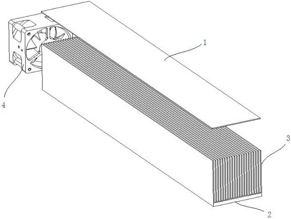
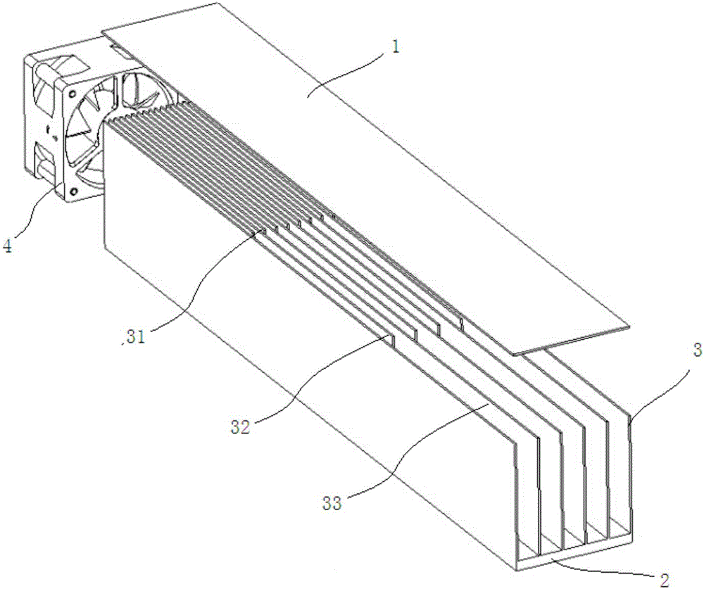
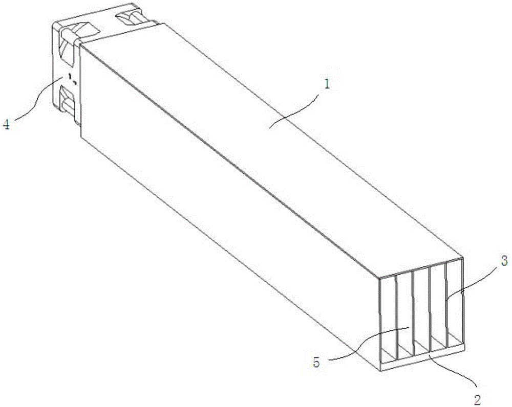
[0021] Embodiment 1: as figure 2 , image 3 As shown, this embodiment provides a novel cooling fin flow channel structure, the flow channel structure includes a flow channel cover plate 1, a flow channel bottom plate 2, and a plurality of mutually parallel channels located between the flow channel cover plate and the flow channel bottom plate The fins 3 are perpendicular to the flow channel cover plate 1 and the flow channel bottom plate 2; the two ends of the flow channel structure are the air inlet 5 and the air outlet; in this embodiment, the air outlet A fan 4 is provided on the end face for sucking cooling air into the flow channel (flow channel structure);

[0022] In this embodiment, the flow channel structure is evenly divided into three flow channel parts along the length direction, wherein the flow channel part near the air inlet is a low-temperature section, and the flow channel part near the air outlet is a high-temperature section. The flow channel part between...

Embodiment 2

[0025] Embodiment 2: The difference from Embodiment 2 is that the novel cooling fin channel structure provided by this embodiment is divided into two channel parts along the length direction, among which the channel part near the air inlet 5 is a low-temperature section, and the channel part near the outlet The flow channel part of the tuyere is a high-temperature section, and the fin spacing in the low-temperature section is larger than the fin spacing in the high-temperature section.

[0026] In this embodiment, both the flow channel bottom plate 2 and the flow channel cover plate 1 are heat-conducting contact surfaces in contact with the heat-generating device, and simultaneously transfer heat to each fin 3 arranged in parallel.


PUM


Abstract

The invention relates to cooling devices, in particular to a novel cooling fin runner structure. The runner structure is divided into at least two runner parts in the length direction, intervals between fins in the runner part close to an air inlet are larger, and therefore the flow resistance of the runner part at the air inlet is reduced, and under the situation that the fan power is not changed, the supply air rate and the air speed in the whole fin runner can be effectively increased relative to an original runner structure; meanwhile, due to the fact that the closer the fins in the runner part are to the air outlet of the runner structure, the smaller the intervals of the fins are, the number of the fins is relatively large, and relative to the runner part at the air inlet, the contact surface of the runner fins with cooling air is increased, and the cooling effect is further enhanced. By means of the structure, under the situation that the fan power is not changed, the highest temperature (generally, a heating device close to the air outlet of the fin runner will have the highest temperature) of the heating device can be effectively reduced.

Description

technical field [0001] The invention relates to a heat dissipation device, in particular to a novel flow channel structure of heat dissipation fins. Background technique [0002] Due to the limitation of the whole machine structure layout of some equipment (such as phased array radar), in order to meet the heat dissipation requirements of the heating device and the space structure of the whole machine at the same time, it is often necessary to use rectangular fins with air inlets and air outlets on both ends. In the specific application, the rectangular fin flow channel is set in parallel contact with the heating device, and a fan is installed at the air outlet of the rectangular fin flow channel, so that the cooling air enters from the air inlet and passes through the rectangular fin flow channel. The cooling air will take away the heat of the heating device located on the heat-conducting contact surface, but this rectangular flow channel has the following disadvantages co...

Claims


Application Information

Patent Timeline
Patent Type & Authority Applications(China)
IPC IPC(8): H05K7/20
CPCH05K7/20409
Inventor 夏辉吴凤鼎管玉静
Owner 成都雷电微力科技股份有限公司
Why Eureka
Try Eureka