
High-efficiency device for water removal from flue gas

A high-efficiency, flue gas technology, used in the separation of dispersed particles, chemical instruments and methods, separation methods, etc., can solve the problems of low precision, low refrigeration efficiency, poor refrigeration effect, etc., to ensure the sealing effect, improve refrigeration efficiency, The effect of increasing the contact area

Inactive Publication Date: 2016-10-19
QINGDAO MINGHUA ELECTRONICS INSTR
View PDF6 Cites 6 Cited by
  • Summary
  • Abstract
  • Description
  • Claims
  • Application Information

AI Technical Summary

Problems solved by technology

[0004] (1) Traditional flue gas dehydration device has low cooling efficiency and poor cooling effect
It takes at least 30 minutes to cool down from 30°C to 0°C in the air, and it is difficult to keep the refrigeration temperature at 0°C as the high-temperature flue gas is introduced.
[0005] (2) The traditional flue gas dehydration device is bulky and heavy, which is not suitable for portable use
[0006] (3) The traditional flue gas dehydration device needs to manually discharge the condensed water in the water storage bottle on a regular basis, which is inconvenient to operate repeatedly
[0007] (4) Due to the poor overall temperature control stability and low precision of the traditional flue gas water removal device, it is easy to form deposits in the gas path, which will block the gas path in the long run and prevent the condensed water from being discharged.

Method used


Image

  • High-efficiency device for water removal from flue gas
  • High-efficiency device for water removal from flue gas

Examples


Embodiment Construction

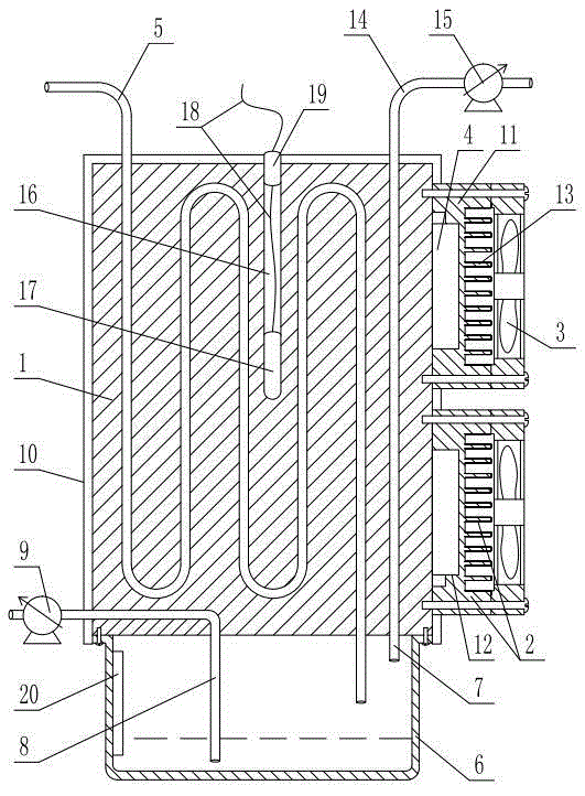
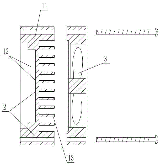
[0029] As shown in the figure, the high-efficiency flue gas dehydration device includes a refrigeration block 1, a fan 3 is installed on the outer wall of the refrigeration block through a mounting part 2, and a semiconductor cooling chip 4 is clamped between the outer wall of the cooling block and the mounting part. The refrigerating surface of the sheet is set close to the side wall of the refrigerating block, the heating surface of the semiconductor refrigerating sheet is set facing the fan, an air channel 5 is arranged in the refrigerating block, and a water storage bottle 6 connected with the output end of the air channel is sealed and connected to the lower end of the refrigerating block. The top of the water bottle is communicated with an air outlet pipe 7, and the bottom of the water storage bottle is communicated with a drain pipe 8, and a drainage mechanism is installed on the drain pipe.

[0030]This high-efficiency flue gas dehydration device achieves a moderate vol...


PUM


Abstract

The invention discloses a high-efficiency device for water removal from flue gas. The device includes refrigeration block; the outer wall of the refrigeration block is provide with a fan through an installation piece; a semiconductor refrigeration piece is installed between the outer wall of the refrigeration block and the installation piece in clamping arrangement; the refrigeration surface of the semiconductor refrigeration piece is tightly against the side wall of the refrigeration block; the heating surface of the semiconductor refrigeration piece is arranged towards a fan; an airway is arranged in the refrigeration block; the lower end of the refrigeration block is tightly connected with a water storage bottle communicated with an output end of the airway; an air outlet pipe is communicated with the upper part of the water storage bottle; the bottom of the water storage bottle is communicated with a water drainage pipe; and the water drainage pipe is provided with a water drainage mechanism. The high-efficiency device for water removal from flue gas has the advantages of moderate volume, effective removal by filtration of the moisture in the flue gas, high water removal speed, good water removal efficiency and simple operation.

Description

technical field [0001] The invention relates to a high-efficiency flue gas water removal device. Background technique [0002] With the improvement of the country's industrialization level, air pollution has become more and more serious. The environmental protection department has also increased its measurement of flue gas every year. In the process of flue gas measurement, the moisture contained in the flue gas will have a great impact on the measurement results, so it must be removed with a corresponding water removal device. [0003] The existing flue gas dehydration technology is the condensation method, which quickly cools the flue gas below the dew point, and the water vapor in the flue gas will condense and precipitate. Traditional flue gas dehydration devices generally have the following defects: [0004] (1) The cooling efficiency of the traditional flue gas dehydration device is low, and the cooling effect is poor. It takes at least 30 minutes to cool down from...

Claims


Application Information

Patent Timeline
Patent Type & Authority Applications(China)
IPC IPC(8): B01D53/26
Inventor 徐军丁万生丁大伟史水合叶兵张迪生叶铠王丽媛奚务俭
Owner QINGDAO MINGHUA ELECTRONICS INSTR
Learn More