Centrifugal fan

A centrifugal fan and distance technology, applied in the direction of mechanical equipment, machine/engine, liquid fuel engine, etc., can solve the problems of environmental noise pollution, strong noise, etc., and achieve the effect of reducing rotation noise, improving efficiency, and reducing amplitude

Inactive Publication Date: 2016-10-19
CHONGQING DONGHONGXIN TECH
View PDF0 Cites 2 Cited by
  • Summary
  • Abstract
  • Description
  • Claims
  • Application Information

AI Technical Summary

Problems solved by technology

[0004] However, the ventilation will also be accompanied by strong noise, which brings serious noise pollution to the environment.

Method used


Image

  • Centrifugal fan
  • Centrifugal fan
  • Centrifugal fan

Examples


Embodiment 1

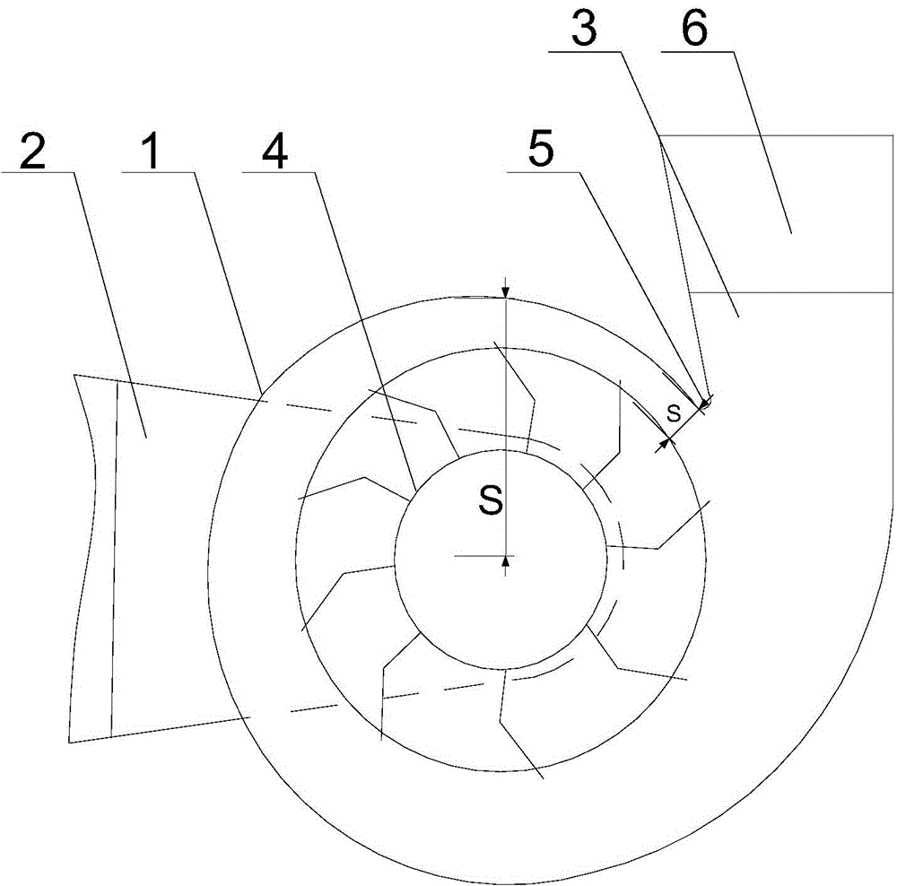
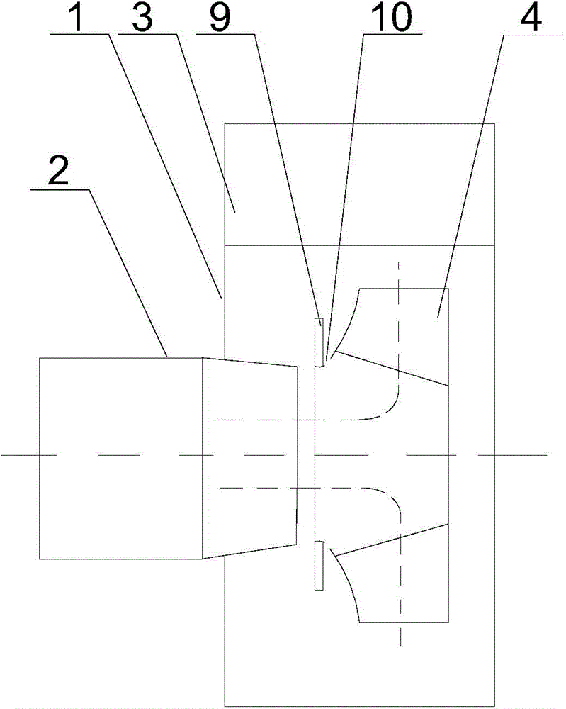
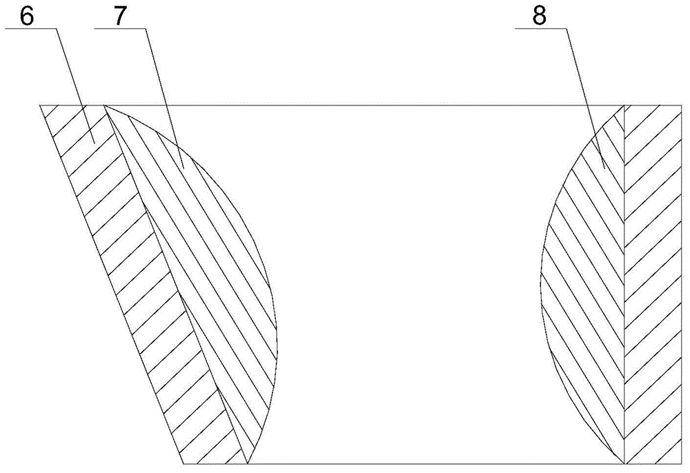
[0023] Such as Figure 1 to Figure 3 As shown, this embodiment includes a volute 1 and an impeller 4 fixed in the volute 1, and the two sides of the volute 1 are respectively provided with a horizontal air inlet 2 and a vertical air outlet 3. A volute tongue 5 is arranged between the volute 1 and the air outlet 3, and a muffler tube 6 is threadedly connected to the end of the air outlet 3, and a 1 / 2 inner wall of the muffler tube 6 near the side of the volute tongue 5 is installed The first muffler 7 is fixed with a second muffler 8 on the remaining half of the inner wall of the muffler cylinder 6. The longitudinal sections of the first muffler 7 and the second muffler 8 are arc-shaped, and the first muffler The distance between the highest point of the sound-absorbing member 7 and the inner wall of the sound-absorbing cylinder 6 is A, and the distance between the highest point of the second sound-absorbing member 8 and the inner wall of the sound-absorbing cylinder 6 is B, an...


PUM


Abstract

The invention discloses a centrifugal fan. The centrifugal fan comprises a volute and an impeller, a volute tongue is disposed between the volute and an air outlet, a silencing barrel is in a threaded connection with the end of the air outlet, a first silencing piece is installed in the 1/2 area of the inner wall, which is at one side close to the volute tongue, of the silencing barrel, a second silencing piece is fixed in the remaining 1/2 area of the inner wall of the silencing barrel, the distance between the highest point of the first silencing piece and the inner wall of the silencing barrel is A, the distance between the highest point of the second silencing piece and the inner wall of the silencing barrel is B, and the relationship between A and B satisfies A>B. The centrifugal fan also comprises a flow baffle loop fixed on the impeller, a flow discharge gap is disposed in the impeller, and the flow discharge gap faces the lower end of the flow baffle loop. The centrifugal fan is advantageous in that, high decibel rotation noise generated by high-speed air flow effecting upon the volute tongue can be eliminated by the first silencing piece, low decibel rotation noise can be eliminated by the second silencing piece, and though differentiated processing of air flow layers with different speeds in the volute, quiet and stable output of air flow at the air outlet is ensured.

Description

technical field [0001] The invention relates to ventilation equipment, in particular to a centrifugal fan. Background technique [0002] The centrifugal fan is mainly composed of: impeller, casing, coupling and shaft. The impeller is the main working part that generates wind pressure and transmits energy; the casing is mainly used to introduce gas and discharge gas, and at the same time convert part of the kinetic energy of the gas into pressure energy; the coupling is used to connect the motor and fan to transmit torque; the shaft is installed and Fixed impeller, through coupling and motor. [0003] When the impeller rotates, the gas between the blades of the centrifugal fan is subjected to centrifugal force to obtain kinetic energy (dynamic pressure head) and is discharged from the periphery of the impeller, guided by the volute-shaped casing, so that it flows to the outlet of the fan, so that it flows in the center of the impeller. Negative pressure is formed, so that t...

Claims


Application Information

Patent Timeline
Patent Type & Authority Applications(China)
IPC IPC(8): F04D29/66F04D29/44F04D29/28
Inventor 彭君秀
Owner CHONGQING DONGHONGXIN TECH
Why Eureka
Try Eureka