
Ultrasonic imaging method and device

An ultrasonic imaging and ultrasonic technology, applied in ultrasonic/sonic/infrasonic diagnosis, sonic diagnosis, infrasonic diagnosis, etc., can solve the problem of uneven image resolution, and achieve the effect of improving uniformity and quality

Active Publication Date: 2016-10-26
CHENGDU YOUTU TECH
View PDF4 Cites 9 Cited by
  • Summary
  • Abstract
  • Description
  • Claims
  • Application Information

AI Technical Summary

Problems solved by technology

[0004] In view of this, the present invention provides a method of ultrasonic imaging, which solves the problem of inhomogeneous image resolution, makes the quality of ultrasonic images better, especially the uniformity of ultrasonic images is significantly improved

Method used


Image

  • Ultrasonic imaging method and device
  • Ultrasonic imaging method and device
  • Ultrasonic imaging method and device

Examples


Embodiment 1

[0020] The ultrasonic imaging method of the embodiment of the present invention includes controlling two or more array elements on the probe to emit ultrasonic waves to form unfocused cylindrical waves; each cylindrical wave is realized with more than one aperture respectively, and After the surface wave, the array element in the current aperture is used to receive the echo; the echo is synthesized through the aperture to realize the transmission and reception of double point-by-point focusing images.

[0021] In this embodiment, the center of the generated unfocused cylindrical wave can be on the surface of the probe, or can be on the surface of the probe. The number of array elements used to transmit cylindrical waves each time is less than or equal to the number of system transmission channels.

[0022] As a preferred mode of this embodiment, the number of array elements is usually greater than 4, and we will record this number as N in the following description.

[0023] E...

Embodiment 2

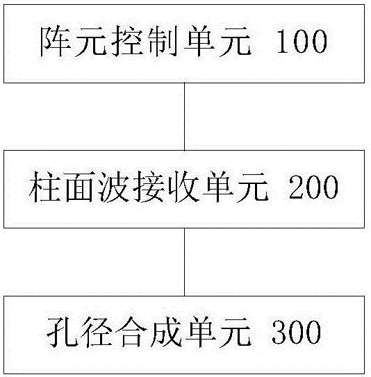
[0041] The present invention also provides an ultrasonic imaging device, such as figure 1 shown, including:

[0042] An array element control unit 100, configured to control two or more array elements on the probe to emit ultrasonic waves to form unfocused cylindrical waves;

[0043] The cylindrical wave receiving unit 200 is used to realize each cylindrical wave with more than one aperture respectively, and use the array element in the current aperture to receive the echo after transmitting the cylindrical wave;

[0044] The aperture synthesis unit 300 is configured to synthesize the echoes through the aperture to realize the dual point-by-point focusing image for transmission and reception.

[0045] As a preferred implementation manner of this embodiment, in order to save costs, the probe may be a general-purpose probe.

[0046] It should be noted that this embodiment is a device invented by using the method of Embodiment 1, and its specific implementation details and furt...


PUM


Abstract

The invention discloses an ultrasonic imaging method and a device thereof. The method comprises the following steps: transmitting ultrasonic waves by virtue of two or more array elements on a probe, so that un-focused cylindrical waves are formed; separately achieving each cylindrical wave by virtue of one or more aperture, and after transmitting the cylindrical waves, receiving echoes by virtue of the array element in the current aperture; and synthesizing the echoes by virtue of the aperture, so that a dual-pointwise focus image is transmitted and received. The device comprises an array element control unit, a cylindrical wave receiving unit and an aperture synthesis unit. With the application of the ultrasonic imaging method provided by the invention, the dual-pointwise focus image can be transmitted and received, so that ultrasonic images are better in quality; and specifically, the uniformity of the ultrasonic images is significantly improved.

Description

technical field [0001] The invention relates to the technical field of ultrasonic imaging. Background technique [0002] The basic principle of ultrasonic imaging is: ultrasonic equipment emits ultrasonic pulses to the human body by exciting the ultrasonic transducer, and the ultrasonic pulses propagate in a certain direction; according to the delay time and strength of the echoes, the distance and nature of the body tissues can be judged . After processing by electronic circuits and computers, an ultrasound image as we understand it is formed. [0003] At present, in the ultrasound imaging market, almost all products use simultaneous excitation of multiple array elements (usually more than 32 channels) to form a focused single-directional transmission beam, and form the strongest transmission signal at the transmission focal point. This type of emission usually produces a very good image at the focal point of the emission, resulting in high resolution. However, at a plac...

Claims


Application Information

Patent Timeline
Patent Type & Authority Applications(China)
IPC IPC(8): A61B8/00
CPCA61B8/4444A61B8/4483A61B8/4488A61B8/5207
Inventor 吴哲
Owner CHENGDU YOUTU TECH
Learn More