A kind of air distribution plate and reactor thereof

A technology of airflow distribution plate and distribution plate, which is applied in the direction of chemical instruments and methods, chemical/physical processes, etc., can solve the imbalance of circumferential flow state and axial flow state, cannot form a three-dimensional bed overall circulation, and the force of a circular plate is stronger than that of a shell. Body difference and other issues, to achieve the effect of no dead zone, safe and scientific space layout, and long production cycle

Active Publication Date: 2019-03-26
THE CHALLENGE PETROCHEM MACHINERY CORP
View PDF5 Cites 1 Cited by
  • Summary
  • Abstract
  • Description
  • Claims
  • Application Information

AI Technical Summary

Problems solved by technology

[0007] The distribution plate is a circular plate-shaped structure, and there are two main problems: one is that the production capacity is limited, and two kinds of through holes need to be designed on the same plate. The granular products on the top flow down smoothly through the through hole. With the increase of production capacity, the two channels of ascending and descending will be randomly blocked; second, the side of the circular plate bears less force than the shell and is easy to deform. The structure and airflow deviated from the original design
[0009] One is the three-dimensional non-equilibrium of the process gas fluidized bed. The process gas forms a spirally rising air flow in the funnel of the distribution plate. The energy loss of the swirling flow in the upward movement causes the circumferential flow state and the axial flow state to be unbalanced, so that from The material from top to bottom gradually generates particles during the reaction, and the coarse particles flow to the surrounding shell wall under the centrifugal action of the swirling flow, which easily causes the radial flow state to be unbalanced
Second, it is difficult to control the airflow pressure at the opening of the distribution plate. This is because the funnel-shaped inverted conical structure makes the space under the distribution plate gradually expand during the rising process, and the process gas under the distribution plate is rising. In the process, the total amount of process gas under the distribution plate is gradually reduced because part of it flows out from the radial opening, so that the air pressure is significantly reduced
The third is that the funnel of the distribution plate goes deep into the lower head to form an overlapping set relationship. The process gas coming in from the head strongly scours the bottom of the funnel due to space constraints, causing strong changes in the air flow pattern and vibration of the funnel, and the structure caused by vibration fatigue Loosening or cracking will generate some additional process gas channels, disturbing the original fluidized bed design, and entering a vicious cycle of structure and process
In addition, the original distribution plate also has some other problems that are not easy to install and adjust
[0010] The reason for the analysis of the above problems is that the structure design of the distribution plate mainly highlights the function of the funnel shape for collecting product particles, while ignoring its influence on the air flow, and ignoring the role of the process from the perspective of emphasizing the results
Some analysis pointed out that due to the influence of the side wall effect, the flow structure of the two-dimensional fluidized bed is quite different from that of the three-dimensional fluidized bed. The air vortex can only develop in the two-dimensional space, and the large-scale flat air vortex is more likely to appear in the bed.
Therefore, it is easy to form unstable fluidization conditions such as throttling in a two-dimensional bed, and it is impossible to form an overall circulation similar to a three-dimensional bed.

Method used


Image

  • A kind of air distribution plate and reactor thereof
  • A kind of air distribution plate and reactor thereof
  • A kind of air distribution plate and reactor thereof

Examples


Embodiment 1

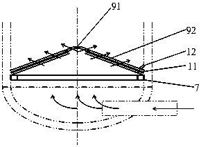
[0041] One of the specific embodiments of an air distribution plate of the present application, refer to figure 1 As shown, the structure is improved and formed by a flat air distribution plate. The innovation of the present application is that the air distribution plate includes a convex structure 91 protruding upward along the central axis of the air distribution plate and The peripheral edge of the structure 91 extends downward to the distribution plate body structure 92 of the inner wall of the cylinder 1 of the reactor. The innovative air distribution plate and the lower head of this application form a mouth-to-mouth enclosed large space relationship, which eliminates the original funnel-shaped distribution plate and goes deep into the lower head to form an overlapping set of narrow gap relationship structure, which improves the view from the bottom of the reactor After the incoming process gas enters the large space, the flow rate is reduced, the pressure is equalized, and...

Embodiment 2

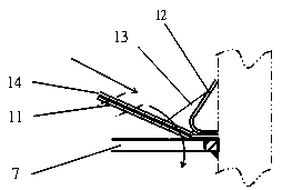
[0052] The second specific implementation manner of an air distribution plate of the present application. The main technical solution of this embodiment is the same as that of Embodiment 1. For the unexplained features in this embodiment, the explanation in Embodiment 1 is adopted and will not be omitted here. Go ahead. The difference between this embodiment and embodiment 1 is that reference Figure 7 The gas flow distribution plate in the reactor structure is shown, wherein the distribution plate body structure 92 is a convex hyperboloid structure.

Embodiment 3

[0054] The third specific implementation manner of an air distribution plate of the present application. The main technical solution of this embodiment is the same as that of Embodiment 1. For the features that are not explained in this embodiment, the explanation in Embodiment 1 is adopted and will not be omitted here. Go ahead. The difference between this embodiment and the first embodiment is that the distribution plate body structure 92 is a concave hyperboloid structure.


PUM


Abstract

The invention discloses a gas flow distribution plate and a reactor with the same. A panel-shaped gas flow distribution plate is modified to form the gas flow distribution plate. The gas flow distribution plate comprises a protrusion structure and a distribution plate body structure. The protrusion structure is upwardly protruded along the central axis of the distribution plate, and the distribution plate body structure downwardly extends along the peripheral edge of the protrusion structure to reach the inner wall of a barrel of the reactor. The gas flow distribution plate and the reactor have the advantages that the distribution plate and a lower seal head are in a mouth-to-mouth enclosed large space relationship with each other, overlapped nested narrow gap structures formed when the original funnel-shaped distribution plate deeply penetrates into an existing lower seal head can be eliminated, flow states of process gas can be improved after the process gas from the bottom of the reactor flows into large spaces, the flow velocity can be reduced, pressures can be balanced, impact vibration can be prevented, then the process gas can flow out from gas flow holes, and accordingly balanced fluidized beds can be formed by materials which move down from the upper portion of the reactor; the gas flow balance, the flowability of granular products and the fatigue resistance of internal structures are taken into accounts, the gas flow distribution plate and the reactor are simple in combination structure and convenient to mount and maintain, the reactor is high in operational flexibility, reaction heat can be quickly evacuated, the safety of shell walls can be protected, and the service lives of the gas flow distribution plate and the reactor can be prolonged.

Description

Technical field [0001] This application relates to the technical fields of various large-scale high-grade reactors used in petroleum refining and chemical industry, coal chemical industry, fertilizer industry and other various chemical equipment, such as fluidized bed polymerization reactors, hydrogenation through catalysts Reactor or desulfurization reactor, etc., especially relates to a gas flow distribution plate and its reactor. Background technique [0002] The chemical reactor includes a cylinder, a head set at both ends of the cylinder, a material inlet and outlet set at the head, an air distribution plate set in the cylinder, and an internal support structure for supporting the air distribution plate, or a cylinder Some of the support structure of the catalyst in the body also includes a corrosion-resistant lining that is welded on the inner surface of the pressure vessel. [0003] In recent years, with the development of petrochemical equipment in the direction of large-s...

Claims


Application Information

Patent Timeline
Patent Type & Authority Patents(China)
IPC IPC(8): B01J8/24B01J8/18
CPCB01J8/1827B01J8/1872B01J8/24B01J2208/00938
Inventor 陈孙艺卢学培张骞
Owner THE CHALLENGE PETROCHEM MACHINERY CORP
Why Eureka
Try Eureka