Convex airflow distribution plate and reactor thereof

A gas distribution plate and gas distribution technology, applied in chemical instruments and methods, refining to remove heteroatoms, chemical/physical processes, etc., can solve the imbalance of circumferential flow state and axial flow state, and cannot form a three-dimensional bed overall circulation, The force of the circular plate is worse than that of the shell, so that there is no dead zone, the space layout is safe and scientific, and the effect of protecting the shell wall is safe.

Active Publication Date: 2016-10-26
THE CHALLENGE PETROCHEM MACHINERY CORP
View PDF6 Cites 1 Cited by
  • Summary
  • Abstract
  • Description
  • Claims
  • Application Information

AI Technical Summary

Problems solved by technology

[0007] The distribution plate is a circular plate-shaped structure, and there are two main problems: one is that the production capacity is limited, and two kinds of through holes need to be designed on the same plate. The granular products on the top flow down smoothly through the through hole. With the increase of production capacity, the two channels of ascending and descending will be randomly blocked; second, the side of the circular plate bears less force than the shell and is easy to deform. The structure and airflow deviated from the original design
[0009] One is the three-dimensional non-equilibrium of the process gas fluidized bed. The process gas forms a spirally rising air flow in the funnel of the distribution plate. The energy loss of the swirling flow in the upward movement causes the circumferential flow state and the axial flow state to be unbalanced, so that from The material from top to bottom gradually generates particles during the reaction, and the coarse particles flow to the surrounding shell wall under the centrifugal action of the swirling flow, which easily causes the radial flow state to be unbalanced
Second, it is difficult to control the airflow pressure at the opening of the distribution plate. This is because the funnel-shaped inverted conical structure makes the space under the distribution plate gradually expand during the rising process, and the process gas under the distribution plate is rising. In the process, the total amount of process gas under the distribution plate is gradually reduced because part of it flows out from the radial opening, so that the air pressure is significantly reduced
The third is that the funnel of the distribution plate goes deep into the lower head to form an overlapping set relationship. The process gas coming in from the head strongly scours the bottom of the funnel due to space constraints, causing strong changes in the air flow pattern and vibration of the funnel, and the structure caused by vibration fatigue Loosening or cracking will generate some additional process gas channels, disturbing the original fluidized bed design, and entering a vicious cycle of structure and process
In addition, the original distribution plate also has some other problems that are not easy to install and adjust
[0010] The reason for the analysis of the above problems is that the structure design of the distribution plate mainly highlights the function of the funnel shape for collecting product particles, while ignoring its influence on the air flow, and ignoring the role of the process from the perspective of emphasizing the results
Some analysis pointed out that due to the influence of the side wall effect, the flow structure of the two-dimensional fluidized bed is quite different from that of the three-dimensional fluidized bed. The air vortex can only develop in the two-dimensional space, and the large-scale flat air vortex is more likely to appear in the bed.
Therefore, it is easy to form unstable fluidization conditions such as throttling in a two-dimensional bed, and it is impossible to form an overall circulation similar to a three-dimensional bed.

Method used


Image

  • Convex airflow distribution plate and reactor thereof
  • Convex airflow distribution plate and reactor thereof
  • Convex airflow distribution plate and reactor thereof

Examples


Embodiment 1

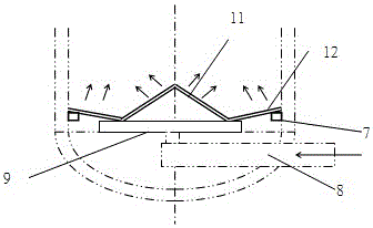
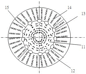
[0039] One of the specific implementations of a convex air distribution plate of the present application, refer to figure 1 and figure 2 As shown, it is formed by the improvement of a flat airflow distribution plate. The innovation of the present application is that the convex airflow distribution plate 10 includes a convex structure 11 protruding upward along the central axis of the convex airflow distribution plate 10 , and a bent structure 12 formed by bending the peripheral side of the convex air distribution plate 10 upward.

[0040] Specifically, the protruding structure 11 is a conical structure. The convex air flow distribution plate 10 is composed of a convex mechanism in the middle and a bending structure 12 on the peripheral side to form a similar convex air flow distribution plate. Studies have shown that the similar convex structure has radial elasticity and can adapt to the deformation of the reactor. Displacement without being distorted and deformed, so its p...

Embodiment 2

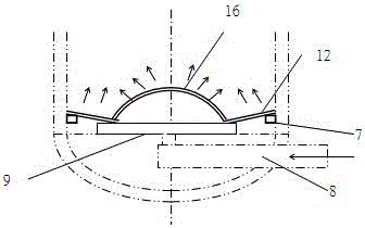
[0051] The second specific embodiment of a convex airflow distribution plate of the present application, the main technical solution of this embodiment is the same as that of embodiment 1, and the features not explained in this embodiment adopt the explanation in embodiment 1, here No further details will be given. refer to image 3 As shown, the difference between this embodiment and Embodiment 1 is that, wherein, the protruding structure 11 is a spherical structure 16 . It can make the process gas flow upwards evenly in the reactor, and at the same time make the generated material particle products collect and discharge from the bottom through the convex air distribution plate, and can also resist vibration fatigue caused by large material flow and fast air velocity. An anti-sediment distribution plate that satisfies pressure drop stability and good fluidization quality.

Embodiment 3

[0053] The third embodiment of a convex airflow distribution plate of the present application, the main technical solution of this embodiment is the same as that of embodiment 1, and the features not explained in this embodiment adopt the explanation in embodiment 1, here No further details will be given. refer to Figure 4 As shown, the difference between this embodiment and Embodiment 1 is that, wherein, the protruding structure 11 is a protruding structure 17 composed of symmetrically arranged concave hyperboloids. It can make the process gas flow upwards evenly in the reactor, and at the same time make the generated material particle products collect and discharge from the bottom through the convex air distribution plate, and can also resist vibration fatigue caused by large material flow and fast air velocity. An anti-sediment distribution plate that satisfies pressure drop stability and good fluidization quality.


PUM


Abstract

The invention discloses a convex airflow distribution plate and a reactor thereof. The convex airflow distribution plate is formed by improving a flat-plate airflow distribution plate and comprises a protruding structure upwards protruding along the central axis and a bent structure formed by upwards bending the circumferential side of the convex airflow distribution plate. The protruding structure is a conical structure, a spherical structure or a protruding structure formed by inwards-concave two hyperboloids which are in symmetric arrangement. The convex airflow distribution plate is conducive to process gas entering from the bottom of the reactor to flow out through airflow holes, materials going down from the upper portion of the reactor and the process gas going up from the lower portion are enabled to contact uniformly and fully, and relatively stable air pressure is maintained; the airflow plate combines airflow balance, granular product fluidity and internal structure fatigue resistance and is simple in combined structure and convenient to mount and maintain, and a supporting member of the airflow plate is more reasonable in stress, high in stability and more safe and scientific in space layout, so that the reactor has high operation flexibility and can withdraw from reaction heat more swiftly, shell wall safety is protected, and service life is prolonged.

Description

technical field [0001] This application relates to the technical field of various large-scale high-grade reactors used in petroleum refining and chemical industry, coal chemical industry, chemical fertilizer industry and other various chemical equipment, for example, polyolefin fluidized bed gas phase reactor, reaction through catalyst A hydrogenation reactor or a desulfurization reactor, etc., especially relates to a convex gas distribution plate and a reactor thereof. Background technique [0002] A chemical reactor, including a cylinder, a head arranged at both ends of the cylinder, a material inlet and outlet arranged on the head, an airflow distribution plate inside the cylinder and an inner support structure for supporting the airflow distribution plate, or a cylinder The supporting structure of the catalyst in the body also includes a surfacing corrosion-resistant lining on the inner surface of the pressure vessel. [0003] In recent years, with the development of pe...

Claims


Application Information

Patent Timeline
Patent Type & Authority Applications(China)
IPC IPC(8): B01J8/02C10G45/04
CPCB01J8/0257B01J8/0278B01J2208/00548B01J2208/00761C10G45/04
Inventor 陈孙艺张骞卢学培
Owner THE CHALLENGE PETROCHEM MACHINERY CORP
Why Eureka
Try Eureka