Welding gun space position and posture self-adaptive adjustment system and method of wheel type welding robot
A welding robot, position and posture adaptive technology, applied in the direction of welding equipment, manipulator, welding rod characteristics, etc., can solve the problems of inability to track and adjust in real time, low efficiency, etc.
- Summary
- Abstract
- Description
- Claims
- Application Information
AI Technical Summary
Problems solved by technology
Method used
Image

Examples
Embodiment Construction
[0039] In order to make the purpose, technical solutions and advantages of the present invention clearer, the present invention will be further elaborated below in conjunction with specific embodiments (not limited to this example) and with reference to the accompanying drawings:
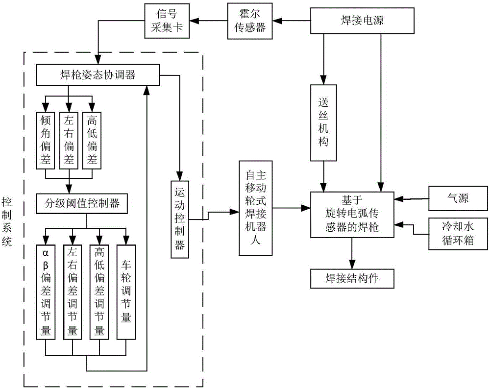
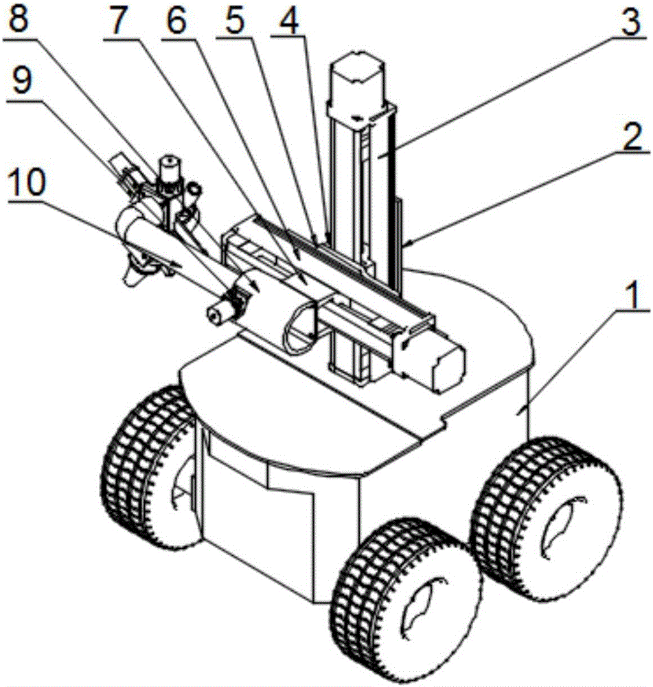
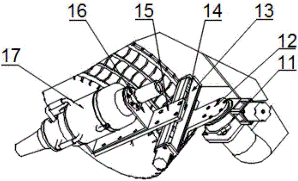
[0040] The basic idea of the present invention is to provide an adaptive real-time adjustment strategy for the space position and posture of the welding torch of an autonomously mobile wheeled welding robot based on a rotating arc sensor, as shown in the attached figure 2 And attached image 3 As shown, the schematic diagram of welding robot assembly. The vertical arm and horizontal arm installed on the roof plate of the Pioneer3DX self-moving trolley are fixedly connected to the α angle adjuster on the moving slider of the horizontal sliding arm, and the β angle adjuster is connected to the α angle adjuster through the hollow arm. The regulator is connected to the fine-tuning arm of the welding ...
PUM
 Abstract
Description
Claims
Application Information
PatSnap Eureka turns technology decisions into work you can execute. Powered by our Innovation Knowledge Graph, it runs expert workflows across engineering, life sciences, materials and intellectual property. Get your review-ready output in minutes.


