Bend cutting device

A cutting device and elbow technology, which is applied in the field of pipe fittings processing, can solve the problems such as the difficulty of clamping, feeding and cutting that the efficient cutting and separation technology of elbows has not been solved satisfactorily, and achieves low production cost and fast clamping. , to ensure the effect of consistency

Active Publication Date: 2016-10-26
王朝永
View PDF8 Cites 1 Cited by
  • Summary
  • Abstract
  • Description
  • Claims
  • Application Information

AI Technical Summary

Problems solved by technology

Due to the long billet of this kind of elbow, and the incision is alternately inclined at different angles relative to the axis of the elbow, it brings great dif

Method used


Image

  • Bend cutting device
  • Bend cutting device
  • Bend cutting device

Examples


Embodiment 1

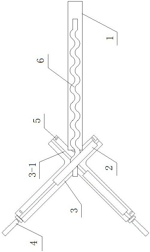
[0030] Such as figure 1 As shown, the elbow cutting device of the present invention includes a rotary laser cutting mechanism 2 and a blank feeding mechanism 1 , and the blank feeding mechanism 1 is located on one side of the rotary laser cutting mechanism 2 . The feeding direction of the billet feeding mechanism 1 is inclined to the rotation axis of the rotary laser cutting mechanism 2, so as to meet the cutting needs of the incision of the multi-joint elbow relative to the axis of the elbow. In view of the fact that the elbow cutting incisions are alternately at two angles relative to the axis of the elbow, the elbow cutting device of the present invention is provided with two rotary laser cutting mechanisms 2, and are set at different angles to alternately cut the elbow. The two rotary laser cutting mechanisms 2 can share a base 3 , and two sliding rails 3 - 1 are intersected on the top surface of the base 3 , respectively slidingly connected with the two rotary laser cutti...

Embodiment 2

[0041] see Figure 6 , as a further improvement of the technical solution of the first embodiment, a rotary mechanism can be set at the bottom of the rotary laser cutting mechanism 2, the rotary mechanism includes a base 3a and a push-pull cylinder 7, and the base 3a is connected to the rotary laser through a thrust bearing The cutting mechanism 2 is connected, and the push-pull cylinder 7 can be fixedly connected with the base 3a through a connector. The telescopic end of the push-pull cylinder 7 is hinged with the rotary laser cutting mechanism 2 through a hinged connector, and a rotation limiter is arranged on the base. In this structure, after the previous cut is completed, the push-pull cylinder 7 is activated, so that the rotary laser cutting mechanism 2 can rotate an angle to cut the next cut. The structure is simpler and brings a series of beneficial effects. The elbow cutting device can also be equipped with a controller (not shown in the figure), which is respective...


PUM


Abstract

The invention discloses a bend cutting device. The bend cutting device comprises rotating type laser cutting mechanisms and a blank feeding-in mechanism; the blank feeding-in mechanism is located on one sides of the rotating type laser cutting mechanisms, the feeding-in direction of the feeding-in mechanism and the rotating axes of the rotating type laser cutting mechanisms are arranged in an inclined manner, the number of the rotating type laser cutting mechanisms is two, and a double-sliding-rail moving mechanism is arranged at the bottoms of the two rotating type laser cutting mechanisms; or one rotating type laser cutting mechanism is adopted, and a rotating mechanism is arranged at the bottom of the rotating type laser cutting mechanism; the laser cutting problems that a bend pipe is irregular in body, and a cutting opening inclines are solved, the high-quality and efficient cutting of the bend pipe is achieved, the error of the cutting opening can be controlled within 0.05 mm, and the cutting opening does not need to be aligned and finished after cutting; and compared with the prior art, the production efficiency can be improved by more than 20 times.

Description

technical field [0001] The invention relates to the technical field of pipe fitting processing, in particular to an elbow cutting device. Background technique [0002] With the progress of society and the development of economy, fluid pipes are widely used in various fields, and have become one of the most used basic parts. The amount of elbows used as connecting parts of fluid pipes is also increasing. Improving production efficiency has become an urgent solution in the industry. The problem. The structure of pipe connection elbows is generally divided into welding elbows and press-formed elbows. For welding elbows, the straight pipe material is usually cut into oblique joints according to the angle of the elbow, and then two or more joints are cut into two or more joints. Butt welding and forming; and forming elbows are generally to bend straight pipes or short joints of straight pipes on a press, or mechanically bend them on a pipe bender, and then cut the two ends into ...

Claims


Application Information

Patent Timeline
IPC IPC(8): B23K26/38B23K26/08B23K37/04B23K101/06
CPCB23K26/083B23K26/0869B23K26/38B23K37/0435B23K2101/06
Inventor 王朝永
Owner 王朝永
Why Eureka
Try Eureka