Plated fiber, carbon fiber, wire harness and plating method

A technology of carbon fiber and fiber, which is applied in the field of plated fiber and wire harness, and can solve the problems of poor metal plating ability, poor adhesion, and poor wettability

Active Publication Date: 2016-10-26
YAZAKI CORP
View PDF12 Cites 2 Cited by
  • Summary
  • Abstract
  • Description
  • Claims
  • Application Information

AI Technical Summary

Problems solved by technology

However, carbon fiber has problems such as poor wettability with the plating solution, and poor leveling ability and adhesion of the metal plating layer.

Method used


Image

  • Plated fiber, carbon fiber, wire harness and plating method
  • Plated fiber, carbon fiber, wire harness and plating method
  • Plated fiber, carbon fiber, wire harness and plating method

Examples


Embodiment Construction

[0035] In conventional electric wires, when tension is applied to the coated fibers during wire harness manufacturing, etc., the fibers may not break and only the metal, that is, the plating, may break. wires to function.

[0036] The present invention was made to solve such conventional problems, and an object of the present invention is to provide a coated fiber and a wire harness capable of preventing breakage of the plating layer without breaking the fiber.

[0037] Below, based on Figure 1~5 Preferred embodiments of the present invention will be described. In addition, this invention is not limited to embodiment shown below, It can change suitably in the range which does not deviate from the summary.

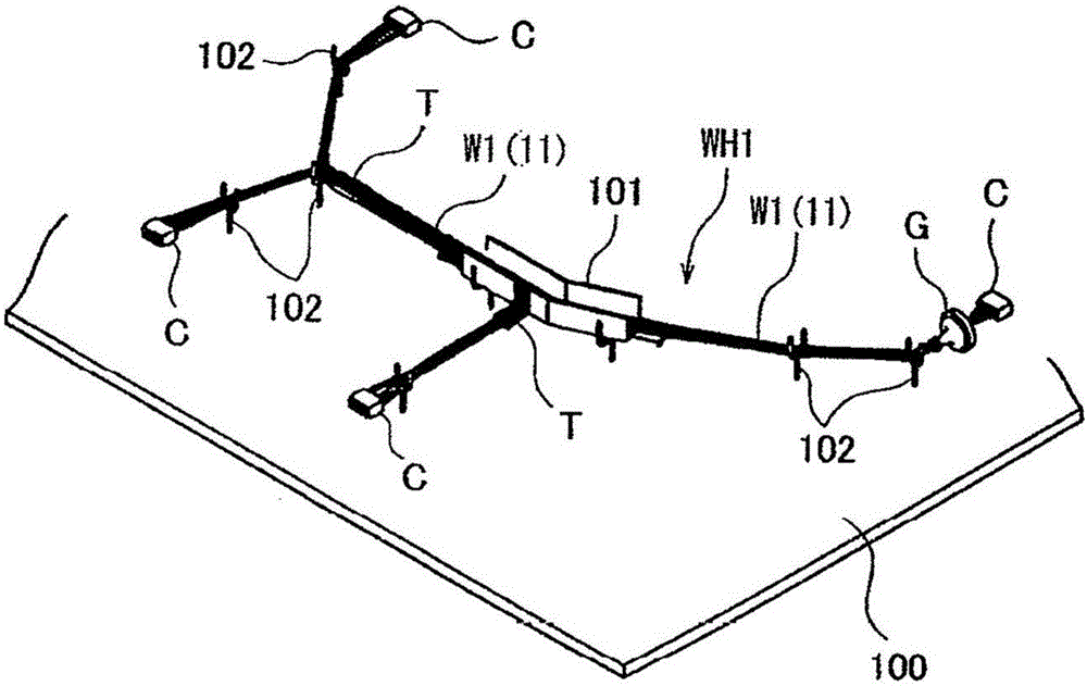
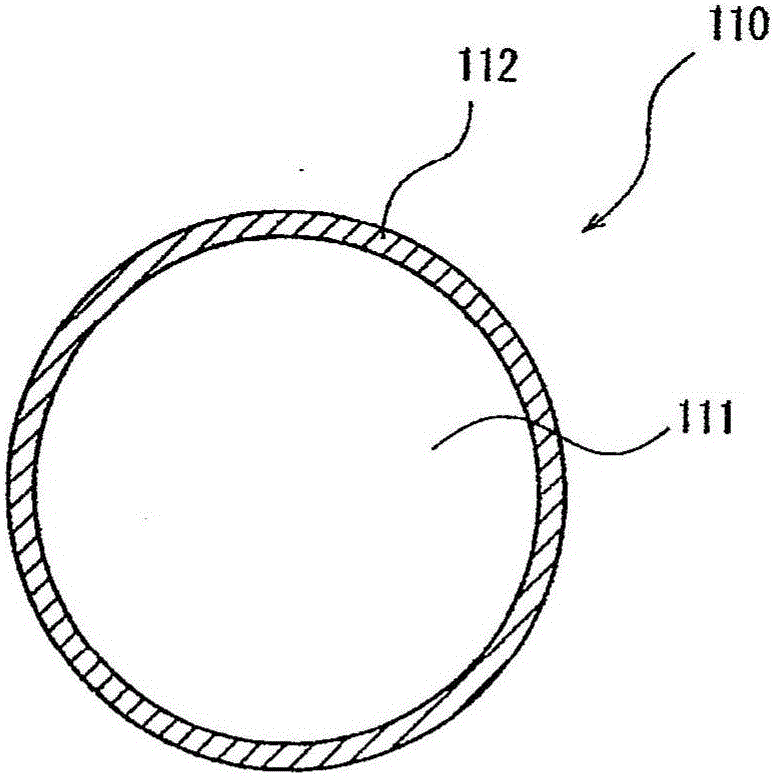
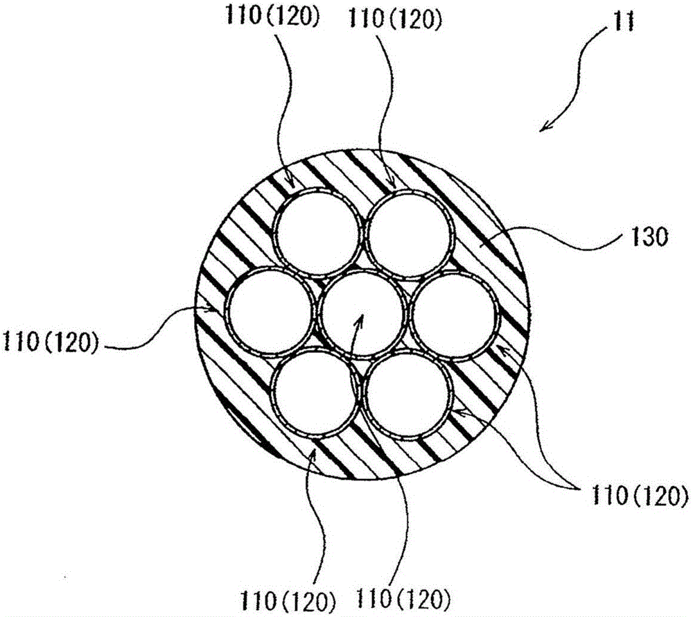
[0038] figure 1 It is a cross-sectional view showing the structure of the plated fiber according to the embodiment of the present invention. In addition, in figure 1 In , for convenience of description, a wiring board is shown in addition to a wiring harness.

[0039...


PUM

PropertyMeasurementUnit
tensile strengthaaaaaaaaaa

Abstract

The invention provides plated fiber, carbon fiber, wire harness and a plating method. A plated fiber that is obtained by applying a metal plating onto a fiber having an elongation percentage which is more than or equal to 1% and less than or equal to 10%. An elongation percentage of the metal plating is higher than the elongation percentage of the fiber. A carbon fiber wherein the surface oxygen amount as a value obtained by dividing an O1S peak intensity measured by X-ray photoelectron spectroscopy by a C1S peak intensity measured by the spectroscopy is more than or equal to 0.097 and less than or equal to 0.138.

Description

technical field [0001] The present invention relates to coated fibers and wire harnesses. [0002] The present invention relates to carbon fibers, wire harnesses and plating methods. Background technique [0003] In recent years, in order to improve fuel efficiency, it is required to reduce the diameter and weight of electric wires, and 0.13sq electric wires and 0.35sq electric wires have been proposed. Tension is applied to such electric wires when they are laid on a wiring board during manufacture of the wire harness. Therefore, a copper alloy is used for the conductor portion in order to be able to withstand the tension, thereby achieving high strength. [0004] However, the increase in the strength of electric wires using copper alloys has reached a limit, and it has been difficult to further reduce the diameter and weight of electric wires. Therefore, it has been proposed that aramid fiber, PBO (poly (p-phenylenebenzobisoxazole)) fiber, and high-strength fiber such as...

Claims


Application Information

Patent Timeline
Patent Type & Authority Applications(China)
IPC IPC(8): D06M11/83D06M11/76H01B1/04H01B7/00C25D5/54D06M101/40
CPCD06M11/76D06M11/83H01B1/04H01B7/0009D06M2101/40C25D5/56C25D3/38H01B1/026C25D7/0607H01B7/0045
Inventor 近藤宏树吉永聪吉川裕辅
Owner YAZAKI CORP
Why Eureka
Try Eureka