
Thermal recovery casing head

A casing head and casing technology, which is applied in earthwork drilling, wellbore/well components, sealing/isolation, etc., can solve the problems that the Christmas tree is easy to sink with the casing of the oil layer, pollute the environment and produce efficiency, and achieve The effect of reliable suspension, convenient use and reasonable structure

Active Publication Date: 2016-10-26
BC P INC CHINA NAT PETROLEUM CORP +1
View PDF6 Cites 5 Cited by
  • Summary
  • Abstract
  • Description
  • Claims
  • Application Information

AI Technical Summary

Problems solved by technology

[0003] The invention provides a casing head for thermal recovery, which overcomes the deficiencies of the prior art, and can effectively solve the problem that the existing thermal recovery casing head is easy to sink with the oil layer casing, pollutes the environment and production The problem of inefficiency

Method used


Image

  • Thermal recovery casing head
  • Thermal recovery casing head

Examples


Embodiment Construction

[0016] The present invention is not limited by the following examples, and specific implementation methods can be determined according to the technical solutions of the present invention and actual conditions.

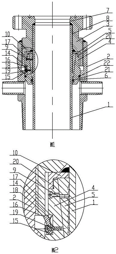
[0017] In the present invention, for the convenience of description, the description of the relative positional relationship of each component is based on the description attached to the description. figure 1 For example, the positional relationship of front, rear, top, bottom, left, right, etc. is determined according to the layout direction of the drawings in the description.

[0018] Below in conjunction with embodiment and accompanying drawing, the present invention will be further described:

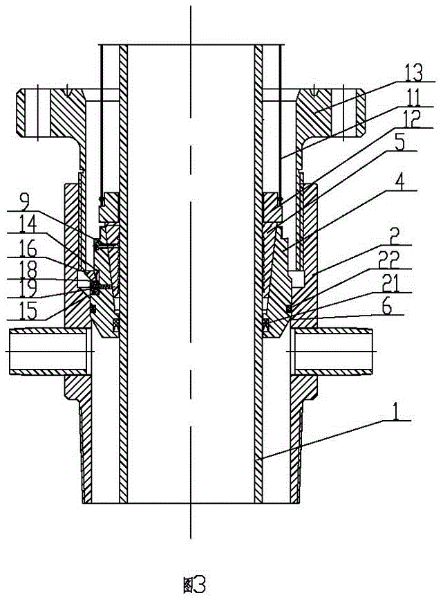
[0019] as attached figure 1 , 2 As shown, the casing head for thermal recovery includes oil layer casing 1, casing body 2, oil tree bottom flange joint 3, hanger 4 and slips 5, and the lower outer side of the oil layer flange joint 3 and the casing body 2 The inside of th...


PUM


Abstract

The invention relates to the technical field of thermal recovery wellhead devices, in particular to a thermal recovery casing head. The thermal recovery casing head comprises an oil-string casing, a casing body, a Christmas tree bottom flanged joint, a hanger and slips, wherein the outer side of the lower portion of the Christmas tree bottom flanged joint is fixed to the inner side of the upper portion of the casing body in a threaded connection mode, the upper end of the oil-string casing is sleeved with a large-diameter hole in the lower portion of the Christmas tree bottom flanged joint, and the oil-string casing is sleeved with a gland located on the inner side of the casing body. By arranging countersunk head threaded shear pins in a countersunk head hole and a horizontal threaded hole to hang the slips, hanging can be achieved reliably; by arranging the Christmas tree bottom flanged joint, mechanical sealing performance is high; machining and installing processes are simplified, and using is convenient; through two groups of welding, connecting strength of the oil-string casing is guaranteed, deformation and sinking of the oil-string casing during frequent gas injection are avoided, weld failure, oil-water leakage and environment pollution are prevented, and the thermal recovery casing head has the advantages of being safe, capable of saving labor, convenient to use and efficient.

Description

technical field [0001] The invention relates to the technical field of thermal recovery wellhead devices, in particular to a thermal recovery casing head. Background technique [0002] Heavy oil reserves in Xinjiang Oilfield account for nearly 25% of the total. At present, the method of high-temperature and high-pressure steam injection is widely used, and the matching is ground anchor prestressed cementing technology. Existing casing heads for thermal recovery generally use a gland to connect the outer side of the upper joint with the casing body, and the lower end of the upper joint is fixed with the upper end of the oil layer casing. However, due to poor cementing quality or after multiple rounds of gas injection The oil layer is subjected to alternating stress, and the bonding strength of the cement sheath between the formation and the oil layer casing decreases, causing the oil layer oil casing to sink, and the Christmas tree that is pressed on the upper end of the oil ...

Claims


Application Information

Patent Timeline
Patent Type & Authority Applications(China)
IPC IPC(8): E21B33/04
CPCE21B33/0422
Inventor 易贵华罗亮王战卫李天鹏
Owner BC P INC CHINA NAT PETROLEUM CORP
Learn More