Broadband wind-induced vibration piezoelectric energy collector

An energy harvester and wind-induced vibration technology, which is applied in wind power generation, wind power generators, wind power motor combinations, etc., can solve the problem that low-frequency vibration piezoelectric sheets cannot generate effective electric energy, etc.

Active Publication Date: 2016-10-26
BEIJING UNIV OF TECH +2
View PDF6 Cites 13 Cited by
  • Summary
  • Abstract
  • Description
  • Claims
  • Application Information

AI Technical Summary

Problems solved by technology

[0012] The purpose of the present invention is to overcome the defect that the prior art does not consider the low-frequency vibration in the low wind speed en

Method used


Image

  • Broadband wind-induced vibration piezoelectric energy collector
  • Broadband wind-induced vibration piezoelectric energy collector
  • Broadband wind-induced vibration piezoelectric energy collector

Examples


Embodiment 1

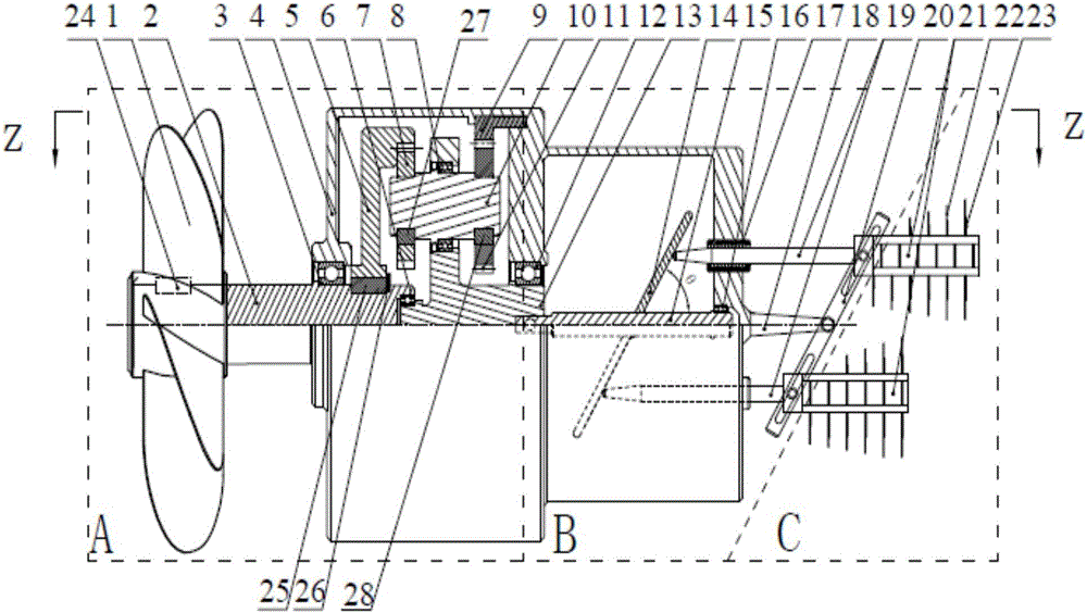
[0090] The movement form of each group of modules is as follows: figure 1 shown.

[0091] From the analysis of motion transfer theory, firstly, the motion input acceleration module generates rotational motion, secondly, the motion output conversion module outputs linear reciprocating motion, and then the energy collection module collects energy for linear reciprocating motion; the motion input acceleration module, motion output conversion module and The movement of the energy harvesting module has very short intervals per unit time, and can be regarded as occurring simultaneously within a unit time, where the unit time is seconds.

[0092] The wind blows the fan (1) to rotate, thereby driving the input shaft (2) to rotate, and the input shaft (2) drives the inner meshing pinion (5) to rotate. The external pinion (7) is driven to rotate by the internal pinion (5). Because external meshing pinion (7) and external meshing bull gear (11) are all fixed on the minor shaft (10), so...

Embodiment 2

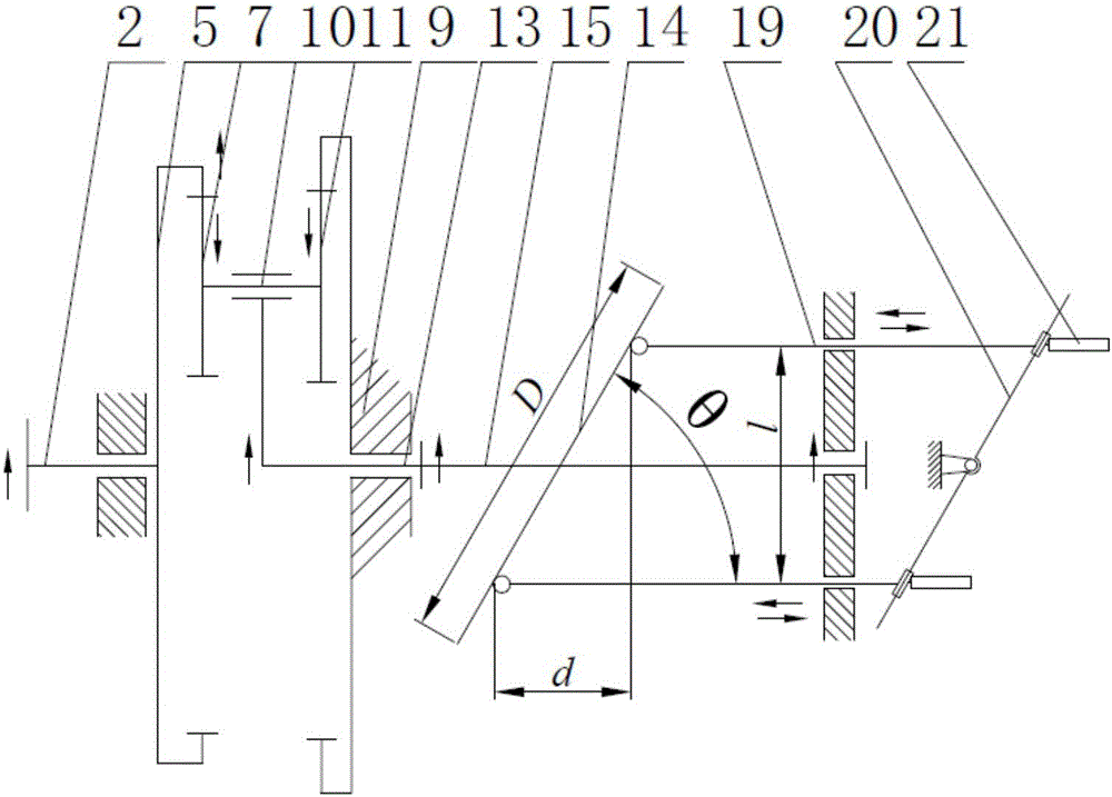
[0109] Such as figure 2 As shown, the movement form of each group of modules is the same as in Embodiment 1.

[0110] In this embodiment, the number of teeth of the internal meshing pinion (5) of the motion input acceleration module Z a =86, the number of teeth of the external and internal meshing pinion (7) Z b =26, the number of teeth of the external gear (11) Z c = 32, internal meshing gear (9) Z d =92, modulus m=1mm

[0111] i a H b = ω a ω H = 1 - i a b H = 1 - Z c Z b Z a ...

Embodiment 3

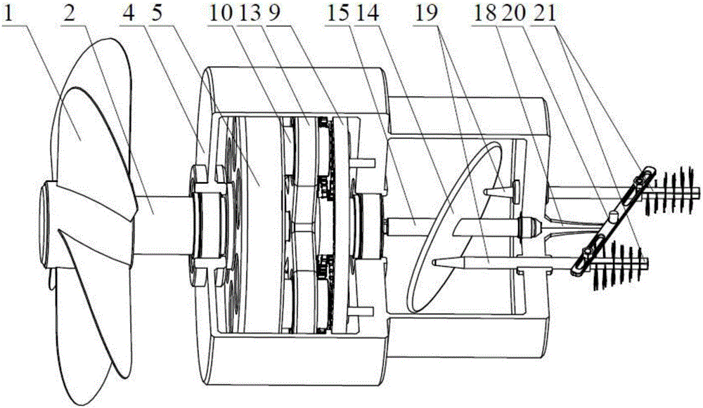
[0122] Such as Figure 9 As shown, the motion forms of the motion input acceleration module and the motion output conversion module are the same as those in Embodiment 1. Expand the energy collection module, increase the amount of energy collection, and expand the frequency bandwidth of wind energy collection, which is suitable for application in natural environments with high wind speed.

[0123] In this embodiment, the motion output conversion module removes the connecting rod (20) and the central base bending rod (18). Add a spring and insert it into the slide bar (19). One end of the spring is fixed on the housing (4), and the other end is fixed at the joint between the slide bar (19) and the base block (21). Figure 11shown. Two sets of (slider bar-base block) assemblies are added, so there are four sets of (slider bar-base block) assemblies in total in this embodiment.

[0124] In this embodiment, the number of teeth of the internal meshing pinion (5) of the motion in...


PUM

PropertyMeasurementUnit
Diameteraaaaaaaaaa
Modulusaaaaaaaaaa

Abstract

A novel broadband wind-induced vibration piezoelectric energy collector is composed of a movement input acceleration module, a movement output conversion module and an energy collecting module. The movement input acceleration module is composed of a fan, an input shaft, a bearing A, an inner engagement small gear, a bearing B, a bearing D, a flat key A, a flat key B, a bolt, a shell, a bearing C and a planetary gear train. The movement output conversion module is composed of an output shaft, an inclined disc, a bearing E, a linear bearing, a central base bent rod, a slide rod and a connection rod. The energy collecting module is composed of a base block, a cantilever beam and a piezoelectric patch. The working process of the broadband wind-induced vibration piezoelectric energy collector includes the steps that a broadband wind-induced vibration piezoelectric vibration energy collector is assembled; and secondly, the fan is blown by natural wind, rotation movement is transmitted to the planetary gear train in the movement input acceleration module, and at the same time, the movement output conversion module and the energy collecting module do corresponding movement. The broadband wind-induced vibration piezoelectric energy collector overcomes the defect that by means of existing design, wind energy in the low-speed state with unceasingly-changing wind speed cannot be effectively collected.

Description

technical field [0001] The invention relates to a wind energy harvester, in particular to a broadband wind-induced vibration piezoelectric energy harvester, which belongs to the technical field of wind power generation and energy collection. Background technique [0002] With the gradual depletion of non-renewable energy and the global environmental pollution it brings, it gradually affects human production and life. It is the consensus of the whole society to use low-pollution or non-pollution renewable energy such as wind energy, water energy, and tidal energy to benefit mankind and promote social development and progress. At the same time, cloud data collection has become increasingly popular in society. The popularization and application of a series of intelligent self-controlled outdoor equipment, such as the Internet of Things, intelligent industrial monitoring, intelligent plateau environment monitoring, and intelligent marine data collection, requires that the equip...

Claims


Application Information

Patent Timeline
IPC IPC(8): F03D9/25
CPCF05B2220/709Y02E10/72
Inventor 曹东兴刘彦琦汪涛姚明辉张伟
Owner BEIJING UNIV OF TECH
Why Eureka
Try Eureka