Two-stage refrigerating circulation system with economizer and oil cooling compression

A circulation system and economizer technology, applied in compressors, refrigerators, compressors, etc., can solve problems such as limiting oil cooling compression cycle performance, achieve the effects of improving equal volume efficiency, simplifying oil cooling system, and improving performance

Inactive Publication Date: 2016-10-26
HUNAN UNIV
View PDF6 Cites 9 Cited by
  • Summary
  • Abstract
  • Description
  • Claims
  • Application Information

AI Technical Summary

Problems solved by technology

However, the amount of fuel injected and the temperature of fuel injected are the key factors affecting the performance of the system, which limits the performance of the oil-cooled compression cycle

Method used


Image

  • Two-stage refrigerating circulation system with economizer and oil cooling compression
  • Two-stage refrigerating circulation system with economizer and oil cooling compression

Examples


Embodiment 1

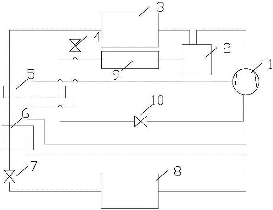
[0015] Such as figure 1 As shown, the exhaust port of compressor 1 is connected to port A of oil separator 2, port B of oil separator 2 is connected to one end of first heat exchanger 3, and the other end of first heat exchanger 3 is connected to port A of economizer 5 respectively. Port A is connected to one end of the second throttling device 4, port B of the economizer 5 is connected to port A of the regenerator 6, port B of the regenerator 6 is connected to one end of the first throttling device 7, and the first The other end of the throttling device 7 is connected to the second heat exchanger 8, the other end of the second heat exchanger 8 is connected to the port C of the regenerator 6, and the port D of the regenerator 6 is connected to the air suction of the compressor 1. The other end of the second throttling device 4 is connected to the port C of the economizer 5, and the port D of the economizer 5 is connected to the gas supply port of the compressor 1 to form a ref...

Embodiment 2

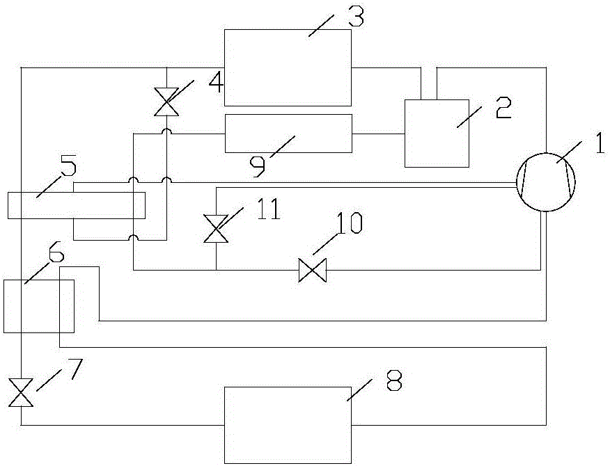
[0019] The exhaust port of compressor 1 is connected to port A of oil separator 2, port B of oil separator 2 is connected to one end of first heat exchanger 3, and the other end of first heat exchanger 3 is respectively connected to port A of economizer 5 It is connected to one end of the second throttling device 4, port B of the economizer 5 is connected to port A of the regenerator 6, port B of the regenerator 6 is connected to one end of the first throttling device 7, and the first throttling device The other end of 7 is connected to the second heat exchanger 8, the other end of the second heat exchanger 8 is connected to the port C of the regenerator 6, and the port D of the regenerator 6 is connected to the suction port of the compressor 1; The other end of the second throttling device 4 is connected to the port C of the economizer 5, and the port D of the economizer 5 is connected to the gas supply port of the compressor 1 to form a refrigerant circuit. The exhaust port ...


PUM


Abstract

The invention provides a two-stage refrigerating circulation system with an economizer and oil cooling compression. The two-stage refrigerating circulation system with the economizer and oil cooling compression comprises a compressor, an oil separator, a first heat exchanger, a second heat exchanger, a third heat exchanger, the economizer, a heat regenerator, a first throttling device, a second throttling device and a third throttling device, and all the components are connected through pipelines. The compressor, the oil separator, the first heat exchanger, the first throttling device, the economizer, the second throttling device and the second heat exchanger form a refrigerant cycle. The compressor, the oil separator, the third heat exchange and the third throttling device form an oil cooling compression cycle. The mass percentage of oil in a mixture (oil and a refrigerant) at an exhaust port of the compressor is 0%-60% and can be regulated. According to the two-stage refrigerating circulation system with an economizer and oil cooling compression, the oil spraying quantity can be increased, compression heat is effectively absorbed by means of the oil cooling compression process, the exhaust temperature of the compressor is decreased, and the isentropic efficiency and isasteric efficiency of the compressor are improved. Through the combination with an air-supply enthalpy increasing cycle of the economizer, the refrigerant in the economizer is evaporated for oil cooling, an oil cooling system is simplified, and the performance of the oil cooling compression cycle is improved.

Description

technical field [0001] The invention relates to the field of refrigeration, in particular to a two-stage refrigeration cycle system with an economizer and oil cooling and compression. Background technique [0002] Refrigeration equipment works under the condition of large temperature difference, and there are phenomena such as low efficiency and high exhaust temperature. The general solution is to use air supplementation to increase enthalpy cycle, improve system efficiency and reduce exhaust temperature through intermediate air supplementation. But when the temperature difference is large to a certain extent, the supplementary air enthalpy increase cycle not only cannot solve the problem of excessive exhaust temperature, but also causes the system to shut down, and also has the problem of very low system performance. Another method is to inject oil into the cylinder of the compressor, and inject a certain amount of oil to absorb a large amount of compression heat to reduce ...

Claims


Application Information

Patent Timeline
Patent Type & Authority Applications(China)
IPC IPC(8): F25B1/10F25B31/00
CPCF25B1/10F25B31/004
Inventor 罗宝军
Owner HUNAN UNIV
Why Eureka
Try Eureka