Turbidity measuring circuit

A technology for measuring circuits and turbidity, which is used in measurement devices, measurement of scattering characteristics, and material analysis by optical means. High rate, the effect of suppressing zero drift

Inactive Publication Date: 2016-10-26
SHENZHEN SINSCHE TECH
View PDF9 Cites 3 Cited by
  • Summary
  • Abstract
  • Description
  • Claims
  • Application Information

AI Technical Summary

Problems solved by technology

[0004] The purpose of the present invention is to provide a turbidity measurement circuit, which solves the technical p

Method used


Image

  • Turbidity measuring circuit
  • Turbidity measuring circuit
  • Turbidity measuring circuit

Examples


Embodiment Construction

[0023] The present invention will be further elaborated below with reference to the accompanying drawings.

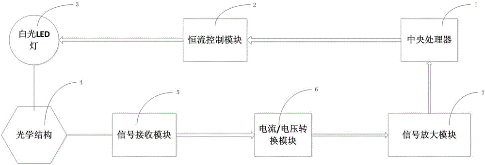
[0024] Please refer to the attached figure 1 to attach Figure 6 , in this embodiment, the turbidity measurement circuit includes: a central processing unit 1, the central processing unit 1 is electrically connected to the constant current control module 2, the constant current control module 2 is electrically connected to the white LED lamp 3, and the white light LED The lamp 3 acts on a signal receiving module 5 through an optical structure 4, the above signal receiving module 5 is coupled to the current / voltage conversion module 6, and the signal converted by the above current / voltage conversion module 6 is sent to the The above-mentioned central processing unit 1, wherein the solution to be detected is placed on the optical structure 4 for scattering. The central processing unit 1 controls the constant current control module 2 to provide a stable current for the w...


PUM


Abstract

The invention discloses a turbidity measuring circuit which comprises a central processor; the central processor is electrically connected to a constant current control module; the constant current control module is electrically connected to a white LED lamp; the white LED lamp acts on a signal receiving module through an optical structure; the signal receiving module is coupled to a current/voltage conversion module; a signal converted by the current/voltage conversion module passes through a signal amplification module and then is delivered to the central processor. The turbidity measuring circuit adopts the white LED lamp as a light source and a first-level silicon photodiode as a signal receiving unit, the white LED lamp is controlled to generate stable brightness through the constant current control module, a differential amplifying circuit is adopted after the signal is received, and interference is suppressed; a circuit land is used as a reference for AD sampling, PGA inside an AD chip is used for controlling gain to achieve high resolution ratio and stable effect, and influence of zero drift and unstable measurement under low turbidity is effectively inhibited.

Description

technical field [0001] The invention relates to the technical field of turbidimeters, in particular to a turbidity measurement circuit for the turbidimeter. Background technique [0002] In the field of measurement technology, there is a turbidity measurement specifically for liquids to obtain liquid characteristic parameters. [0003] However, the light sources of turbidimeters on the market generally use tungsten lamps and LED lamps. In terms of circuit processing, the zero point drift is often large due to improper processing, frequent zero adjustment is required, and the resolution is low. Extremely unstable at low turbidity. Therefore, there is an urgent need in the market for a turbidity measurement system that is stable for low turbidity measurement and has a small zero point drift. Contents of the invention [0004] The purpose of the present invention is to provide a turbidity measurement circuit, which solves the technical problems of large zero point drift and...

Claims


Application Information

Patent Timeline
IPC IPC(8): G01N21/01G01N21/49
CPCG01N21/01G01N21/49
Inventor 李伟坤郑俭锋黄晓平
Owner SHENZHEN SINSCHE TECH
Why Eureka
Try Eureka