
Novel compound switch for high-voltage capacitor switching and working method of novel compound switch

A composite switch and high-voltage capacitor technology, applied in high-voltage/high-current switches, electrical switches, high-voltage air circuit breakers, etc., can solve the problems of reducing the reliability and safety of composite switches, restricting the promotion and use, and improving reliability and reliability. Safety, the effect of eliminating closing inrush current and opening overvoltage, and simplifying control

Active Publication Date: 2016-10-26
STATE GRID CORP OF CHINA +1
View PDF5 Cites 5 Cited by
  • Summary
  • Abstract
  • Description
  • Claims
  • Application Information

AI Technical Summary

Problems solved by technology

[0004] However, the commonly used compound switch generally adopts the topology structure of thyristor parallel mechanical switch. Since the thyristor is too sensitive to the voltage change rate, it is easy to be misconducted and damaged under overvoltage conditions such as lightning strikes. At the same time, this structure also requires a complex trigger circuit. To ensure the synchronization of thyristor triggering, all these factors reduce the reliability and safety of the composite switch to a certain extent, and limit its popularization and use.

Method used


Image

  • Novel compound switch for high-voltage capacitor switching and working method of novel compound switch
  • Novel compound switch for high-voltage capacitor switching and working method of novel compound switch
  • Novel compound switch for high-voltage capacitor switching and working method of novel compound switch

Examples


Embodiment Construction

[0015] The technical solution of the present invention will be further described below in conjunction with the accompanying drawings.

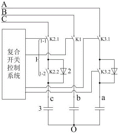
[0016] A new composite switch for high-voltage capacitor switching, including a composite switch control system and a mechanical switch; the composite switch control system is connected to a mechanical switch; the mechanical switch includes a phase A main switch, a C phase main switch, and an A phase auxiliary switch. switch, C-phase auxiliary switch, B auxiliary mechanical switch; one end of the A-phase main switch is electrically connected to A-phase, and the other end is connected to one end of A-phase auxiliary switch; the other end of A-phase auxiliary switch is connected to the opening capacitor; the C-phase One end of the main switch is electrically connected to phase C, and the other end is connected to one end of the auxiliary switch of phase C; the other end of the auxiliary switch of phase C is connected to the opening capacitor; one...


PUM


Abstract

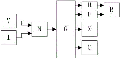
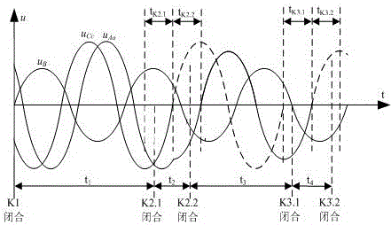
The invention relates to a novel compound switch for high-voltage capacitor switching and a working method of the novel compound switch. The compound switch comprises a compound switch control system, diode strings and mechanical switches, wherein each of A and C two phases is provided with two mechanical switches, namely a primary switch and an auxiliary switch; each primary switch is connected with one diode string in parallel; only one auxiliary mechanical switch is arranged on a B phase for playing an isolating role; and the compound switch control system comprises a voltage and current detection circuit, mechanical switch drive circuits, an operating mechanism energy-storage capacitor charging control circuit, a compound switch state display circuit and a digital control system. By the novel compound switch, voltage zero point turn-on and current zero point turn-off of the compound switch can be achieved; switching inrush current and breaking overvoltage in the switching process are eliminated; and non-arc operation of the mechanical switches can also be achieved. Meanwhile, a thyristor string is replaced with the diode strings; and compared with a traditional compound switch, the novel compound switch has the advantages that complicated trigger circuit is not needed and the problem of the damage caused by over-voltage conduction by mistake of a lightning stroke and the like is solved.

Description

technical field [0001] The invention relates to a novel composite switch used for high-voltage capacitor switching, which belongs to the field of high-voltage switches. Background technique [0002] With the rapid development of the national economy and the continuous improvement of people's living standards, the capacity of the power grid and electrical equipment have increased dramatically. Because the load size and distribution of the power system are different, not only the power supply structure of the grid system is changed, but also the power supply distribution of the grid system is changed, and a large number of reactive components are introduced into the grid system. In order to build a resource-saving and environment-friendly society, improve the utilization rate of power grid resources, and improve the quality of power supply of the power grid, it is necessary to carry out reactive power compensation for the power grid system. [0003] Switching shunt capacitors...

Claims


Application Information

Patent Timeline
IPC IPC(8): H01H33/666H02J3/18
CPCY02E40/30H01H33/666H02J3/18
Inventor 徐东晟邱志人雷志鹏
Owner STATE GRID CORP OF CHINA
Learn More