
Power battery and car with it

A power battery and battery box technology, applied in the field of vehicles, can solve the problems such as the sealing of the lower box and the upper cover bothering developers, the difficulty of welding steel nuts, and the large volume of the battery box, achieving light weight, simple structure, The effect of simplifying the assembly process

Active Publication Date: 2019-06-04
BEIJING ELECTRIC VEHICLE
View PDF4 Cites 0 Cited by
  • Summary
  • Abstract
  • Description
  • Claims
  • Application Information

AI Technical Summary

Problems solved by technology

The battery box in the related art is an aluminum profile box, which has the advantages of light weight and less air hole defects. However, when bolts are required, because the aluminum material is relatively low in strength and high in brittleness compared with steel, if the aluminum material is directly tapped And using steel bolts to fix it often leads to wire stripping and hole edge breakage. At the same time, because the welding quality of aluminum material parts and steel nuts is very poor, it is difficult to directly weld steel nuts and aluminum materials. Fixing methods such as rivet nuts and wire threaded sleeves are used. Due to the high process requirements of the rivet nuts during riveting, the consistency is difficult to guarantee. If the steel wire threaded sleeves are assembled repeatedly or subjected to strong vibration, the threaded sleeves may break.
[0003] Furthermore, the lower box of the battery box in the related art is a sheet metal, cast aluminum or profile aluminum box, and the upper cover is generally made of aluminum or light flame-retardant non-metallic materials. However, due to the large volume of the battery box, The sealing of the lower box and the upper cover has always troubled the majority of developers

Method used


Image

  • Power battery and car with it
  • Power battery and car with it
  • Power battery and car with it

Examples


Embodiment Construction

[0041] Embodiments of the present invention are described in detail below, examples of which are shown in the accompanying drawings, wherein the same or similar reference numerals designate the same or similar elements or elements having the same or similar functions throughout. The embodiments described below by referring to the figures are exemplary and are intended to explain the present invention and should not be construed as limiting the present invention.

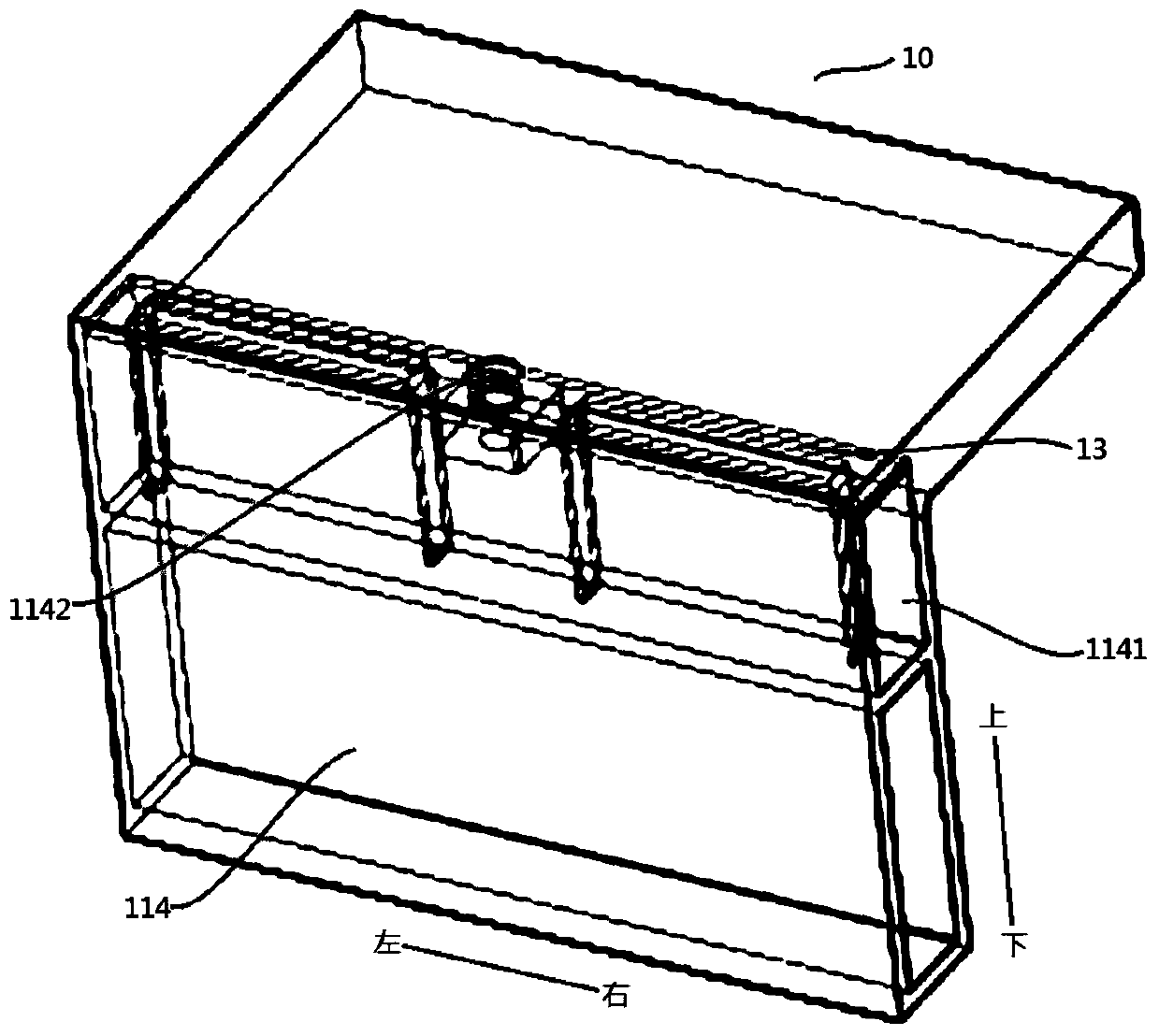
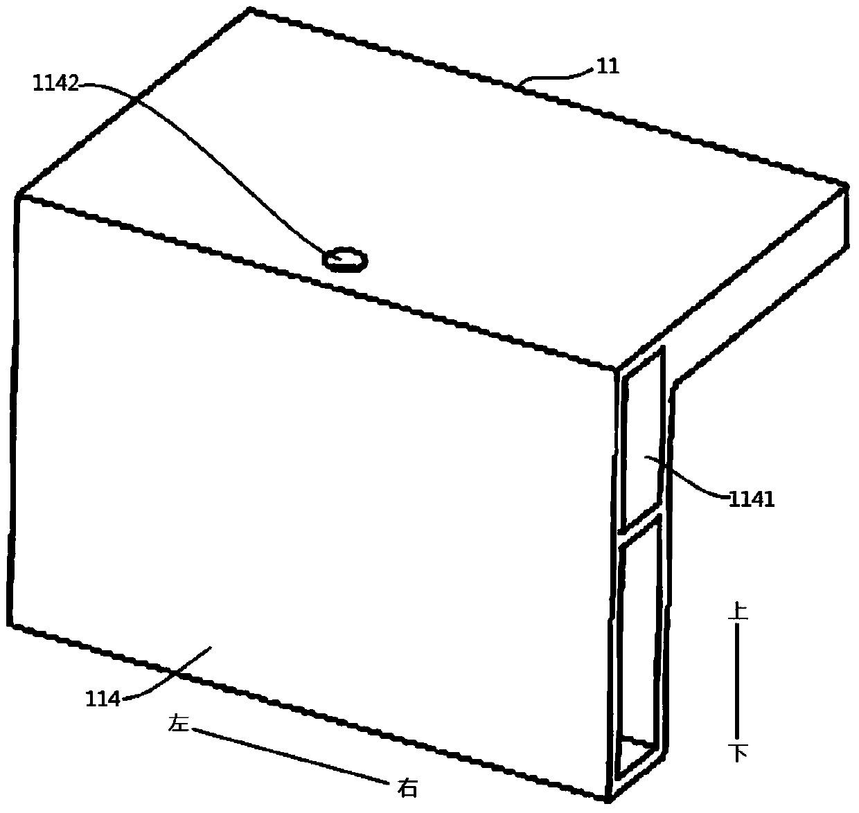
[0042] The following first combines the attached Figure 1 to Figure 8 The power battery according to the embodiment of the first aspect of the present invention will be described in detail.

[0043] Such as figure 1 with Figure 5 As shown, the power battery according to the embodiment of the present invention includes a battery box 10 , a fixing plate 13 , a fixing piece 14 , a fastener 80 , a battery module (not shown) and a sealing strip 70 . Specifically, the battery box 10 includes a lower box body 11 and an...


PUM


Abstract

The invention discloses a power battery and a car with the same. The power battery comprises a battery box, a fixing plate, a fixing part, a fastening part, a battery module and a sealing strip, wherein the battery box comprises a lower box body and an upper cover, the lower box body comprises a plurality of mounting plates, a cavity is defined in at least one of the mounting plates, and the mounting plate is provided with an assembling hole; the fixing plate is fixed in the cavity; the fixing part and the fixing plate are made of the same material and connected through welding; the fastening part penetrates the upper cover and the assembling hole to be connected with the fixing part; the sealing strip is arranged between the upper cover and the lower box body to seal the gap between the upper cover and the lower box body, the sealing strip comprises a body, at least two upper support feet and at least two lower support feet, the upper support feet are respectively abutted against the upper cover, and the lower support feet are respectively abutted against the battery box. The power battery is simple in structure, lightweight, low in cost, reliable in part connection, convenient to mount and demount, good in sealing performance and high in use reliability.

Description

technical field [0001] The present invention relates to the technical field of vehicles, and more specifically, to a power battery and an automobile having the same. Background technique [0002] The power battery can provide the power source for the electric vehicle. The battery box is the carrier for the battery cell and the control unit. Generally, the battery box installed on the chassis of the vehicle has the following requirements: 1) light weight; 2) high protection level; 3) Bench vibration test needs to meet GB31467.3-2005. The battery box in the related art is an aluminum profile box, which has the advantages of light weight and less air hole defects. However, when bolts are required, because the aluminum material is relatively low in strength and high in brittleness compared with steel, if the aluminum material is directly tapped And using steel bolts to fix it often leads to wire stripping and hole edge breakage. At the same time, because the welding quality of ...

Claims


Application Information

Patent Timeline
Patent Type & Authority Patents(China)
IPC IPC(8): H01M2/10
CPCH01M50/20H01M50/24Y02E60/10
Inventor 和爱博
Owner BEIJING ELECTRIC VEHICLE
Learn More