
Electrical connectors for circuit boards

A technology for circuit substrates and electrical connectors, applied in the direction of conductive connection, circuit, connection, etc., can solve the problem of poor contact state of the elastic displacement terminal of the contact arm, poor contact of the target terminal, and the inability to fully obtain the elastic displacement state of the contact arm, etc. problem, to achieve the effect of ensuring the elastic displacement state

Active Publication Date: 2018-05-15
HIROSE ELECTRIC GROUP
View PDF7 Cites 0 Cited by
  • Summary
  • Abstract
  • Description
  • Claims
  • Application Information

AI Technical Summary

Problems solved by technology

If the solder adhering to the surface of the contact arm is solidified, there is a possibility that a sufficient elastic displacement state of the contact arm cannot be sufficiently obtained.
In addition, when the molten solder on the surface of the contact arm further reaches the protruding surface of the contact portion, that is, the contact surface with the mating terminal via the gap between the contact arm portion and the inner wall surface of the groove portion of the protruding wall, there may be Poor contact with the target terminal may be caused
[0008] In addition, in order to prevent corrosion of the solder connection portion between the above-mentioned connection portion and the above-mentioned mounting surface, a coating agent such as resin may be applied to the solder connection portion. On the surface of the contact arm, there is a possibility of causing elastic displacement of the contact arm and poor contact state of the target terminal.

Method used


Image

  • Electrical connectors for circuit boards
  • Electrical connectors for circuit boards
  • Electrical connectors for circuit boards

Examples


Embodiment Construction

[0029] Embodiments of the present invention will be described below based on the drawings.

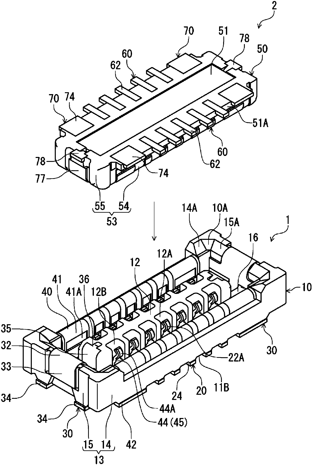
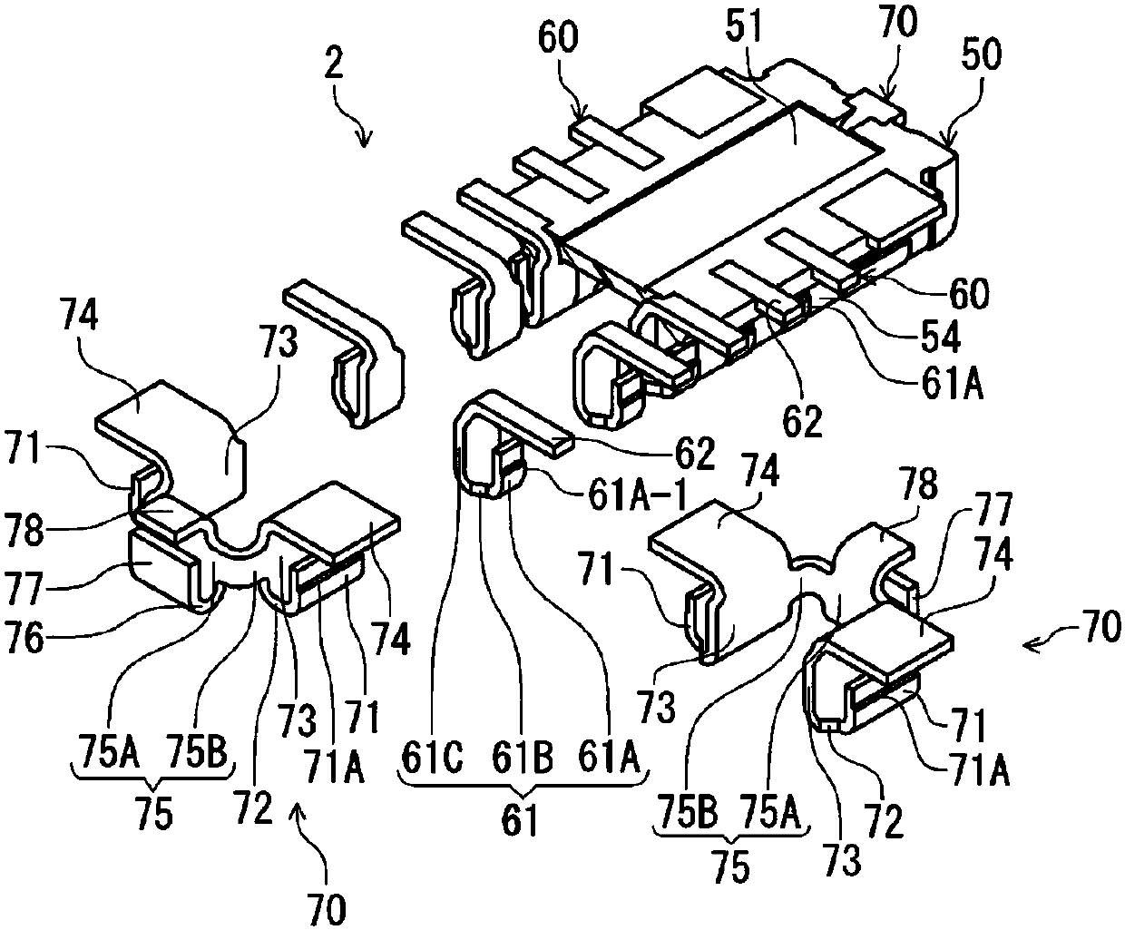
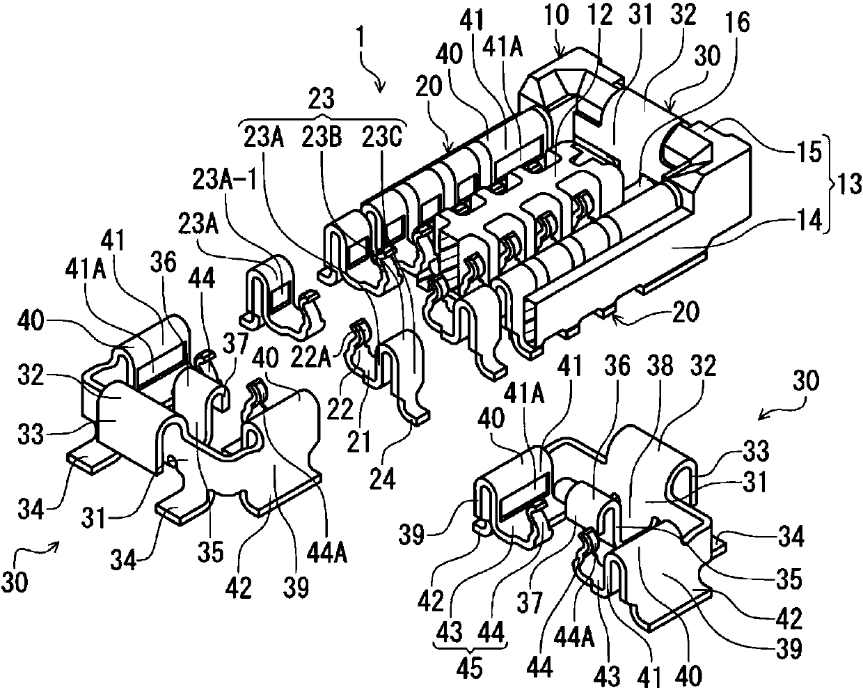
[0030] figure 1 It is a perspective view of the receptacle connector of this embodiment and the plug connector which is a target connector mated with it from above, and shows the state before connector mating. The receptacle connector 1 and the plug connector 2 in this embodiment are electrical connectors for circuit boards respectively disposed on the mounting surfaces of different circuit boards (not shown), and are configured so that they are at right angles to the mounting surfaces of the respective circuit boards. direction( figure 1 The up and down direction in) becomes the connector assembly in the plugging and unplugging direction. In this embodiment, the fitting direction of the plug connector 2 with respect to the receptacle connector 1, that is, figure 1 The direction in which the plug connector 2 moves downward is set as the "connector fitting direction", and the opposit...


PUM


Abstract

The present invention provides an electrical connector for a circuit board that can prevent solder and coating agents from adhering to contact arm portions of terminals. The housing (10) has a bottom wall (11) parallel to the mounting surface of the circuit board, and an upright wall (12) that rises from the bottom wall toward the connector insertion and extraction direction and extends along the length direction of the connector. The wall is formed with a groove portion (12A) that is recessed from the side surface of the upright wall and extends in the connector insertion and extraction direction. The terminal (20) has a base portion (21) that is held by being integrally formed with the bottom wall. The contact arm portion (22) with one end extending in the groove portion along the connector insertion and extraction direction, and the connecting portion (24) formed in the portion extending from the other end of the base portion and capable of being welded and connected to the above-mentioned mounting surface, the erecting wall The groove portion is formed over the entire raised range of the raised wall, and the bottom wall is formed to include a range corresponding to the contact arm portion in the width direction of the connector.

Description

technical field [0001] The present invention relates to an electrical connector for a circuit board arranged on a mounting surface of a circuit board. Background technique [0002] As such an electrical connector for a circuit board, for example, the connector of Patent Document 1 is known. The connector of Patent Document 1 has a housing having a cubic shape, and terminals aligned and held by being integrally formed with the housing in the longitudinal direction of the connector (the longitudinal direction of the housing). This housing has: a bottom wall facing the mounting surface of the circuit board, a quadrangular frame-shaped peripheral wall standing upward from the peripheral portion of the bottom wall, and a connector width direction (with respect to the above-mentioned longitudinal direction of the housing). The central region protrudes upwards from the bottom wall along the lengthwise direction of the connector. A quadrilateral annular space opened upward and sur...

Claims


Application Information

Patent Timeline
Patent Type & Authority Patents(China)
IPC IPC(8): H01R12/71H01R13/46H01R13/02
CPCH01R12/716H01R13/02H01R13/46H01R12/73H01R4/028H01R12/57H01R12/707H01R12/7082H01R12/71H01R13/6275
Inventor 小林勇貴
Owner HIROSE ELECTRIC GROUP
Learn More