Interferometric sensor

A sensor and detector technology, which is applied in the direction of converting sensor output, instruments, and using optical devices to transmit sensing components, etc., can solve problems such as increasing complexity, reducing sensor reliability, and complex signal processing

Inactive Publication Date: 2016-10-26
ABB POWER GRIDS SWITZERLAND AG
View PDF11 Cites 3 Cited by
  • Summary
  • Abstract
  • Description
  • Claims
  • Application Information

AI Technical Summary

Problems solved by technology

While this solution can generally remove all points of ambiguity, operating the light source and detector at three or more wavelengths n

Method used


Image

  • Interferometric sensor
  • Interferometric sensor
  • Interferometric sensor

Examples


Embodiment Construction

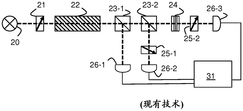
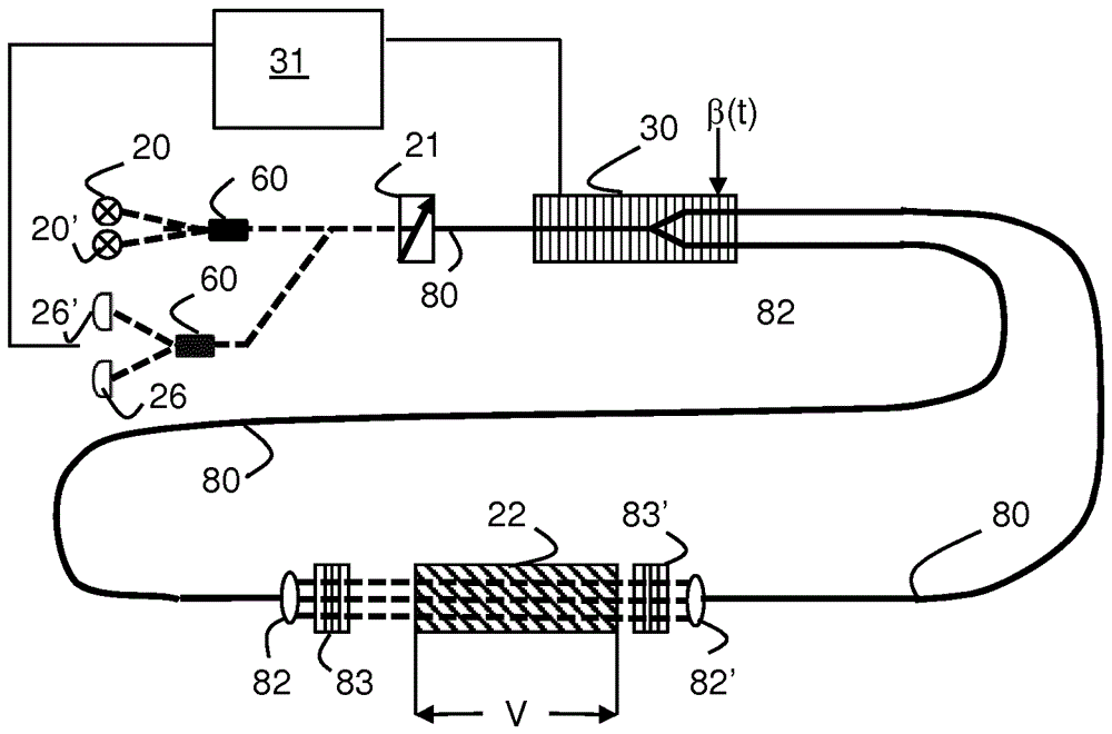
[0036] In the following, the example of an orthogonal polarization interferometer is used to describe the steps of signal manipulation or processing used in the present invention. It should be noted that the basic principles of the described examples apply to many different types of interferometric sensors that otherwise suffer from period-wise ambiguities. Therefore, they can be applied to virtually any type of interferometer (Michelson, Mach-Zehnder, Fabry-Perot, Sagnac, etc.), with only minor differences in implementation or interpretation.

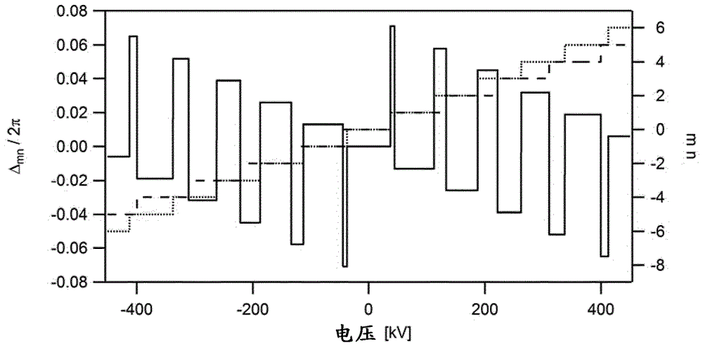
[0037] The output of a polarimetric disturbance sensor is a sinusoidal function of the relative phase shift, which relates to the measured object x. In general, the output at two different wavelengths is

[0038] ,as well as

[0039]

[0040] in and is the relative phase shift, q 1 and q 2 is the inverse response period, and and are at the wavelength λ 1 and lambda 2 The phase bias of the sensor. For brevity and wit...


PUM


Abstract

An interferometric sensor is provided, with one or more wave generators (20, 20') generating at least a first set of two waves both centered at a first wavelength and a second set of two waves both centered at a different second wavelength, and a sensing element (22) whereby a measurand induces a first relative phase shift between the first set of waves and a second relative phase shift between the second set of waves, respectively, at least one detector (26, 26') measuring a first interference signal between the first set of waves and a second interference signal between the second set of waves, and further including a signal processing unit (31) adapted to determine from the first and second interference signals two quantities representative of the principal values of the first and the second relative phase shifts unambiguously within a 2[pi] range, respectively, and to derive a measurand value from their combination.

Description

technical field [0001] The invention relates to interferometric sensors in which the change in the parameter to be measured is related to the relative phase shift between two waves, such as electro-optical voltage sensors or fiber optic current sensors (FOCS) especially for DC voltages. Background technique [0002] Sensors relying on the interference between two waves, usually two orthogonally polarized modes of waves, are known and used in a wide range of technical fields. The relative phase shift between the detector signal of these sensors and the two waves The cosine correlation of . therefore, and Phase shifts (n being an integer, also referred to herein as a cycle counter) produce identical interference outputs and are therefore indistinguishable from each other. Therefore, the unambiguous measurement range of the relative phase shift is limited to the range [0, π]. [0003] For example, bismuth germanate (Bi 4 Ge 3 o 12 or BGO) crystal with its [001] crys...

Claims


Application Information

Patent Timeline
IPC IPC(8): G01B9/02G01D5/26G01D5/353G01R15/24
CPCG01D5/266G01D5/35309
Inventor 顾逊S.V.马彻塞K.博内特A.弗兰克
Owner ABB POWER GRIDS SWITZERLAND AG
Why Eureka
Try Eureka