Single-wing intravenous needle assembling machine

A technology for venous needles and assembly machines, which is applied in the direction of assembly machines, metal processing equipment, manufacturing tools, etc., can solve the problems of complex structure of venous needle assembly machines, insufficient automation, and unreasonable overall design, so as to avoid blockage and ensure The effect of adding glue and saving cost

Pending Publication Date: 2016-11-02
梁启明
View PDF1 Cites 12 Cited by
  • Summary
  • Abstract
  • Description
  • Claims
  • Application Information

AI Technical Summary

Problems solved by technology

[0004] Although the above solution solves the deficiencies of the prior art to a certain extent, the structure of the venous needle assembly machine is relatively complicated, the degree of automation is not high enough, the assembly efficiency is low, it is not conducive to large-scale production, and the overall design is not reasonable enough

Method used


Image

  • Single-wing intravenous needle assembling machine
  • Single-wing intravenous needle assembling machine
  • Single-wing intravenous needle assembling machine

Examples


Embodiment 1

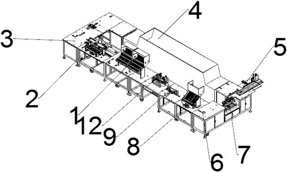
[0041] see figure 1 As shown, a single-wing venous needle assembly machine includes an upper wing device 1 for placing wings into the carrier 13. The upper wing device 1 is the starting point, and the conveyor belt behind the upper wing device 1 is connected with an upper needle. Component 2, the conveyor belt behind the upper needle component 2 is connected to the right-angle transmission component 3, the conveyor belt behind the right-angle transmission component 3 is connected to the oven 4, the conveyor belt behind the oven 4 is connected to the reverse needle detection component 5, and the conveyor belt behind the reverse needle detection component 5 is connected to the carrier The direction changing device 6 is provided with a first gas testing device 7 behind the vehicle direction changing device 6, a sheath assembly 8 is connected to the conveyor belt behind the first gas testing device 7, and a hose assembly assembly 9 is connected to the conveyor belt behind the sheat...

Embodiment 2

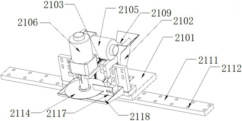
[0043] On the basis of embodiment 1, see figure 2 Shown is a schematic structural view of the needle assembly 2 of this embodiment, including a needle point glue adding device 21, which includes a base 2101, above which is provided a glue tray 2102 for placing glue; also includes a glue adding wheel 2103 , the rubber adding wheel 2103 is set vertically, and the bottom extends into the glue tray 2102; it also includes a rubber upper wheel 2104, the upper rubber wheel 2104 is arranged horizontally, the rubber adding wheel 2103 is driven by the glue adding motor 2105, and the rubber upper wheel 2104 is driven by the glue applying motor Driven by 2106, the upper rubber wheel 2104 is also provided with a squeegee 2107 for scraping off overflowing glue. Below the squeegee 2107, an overflow plate 2108 is arranged, and the overflow plate 2108 communicates with the glue plate 2102. The glue plate 2102 is provided with The glue adding port 2109, the edge of the glue adding plate 2103 i...

Embodiment 3

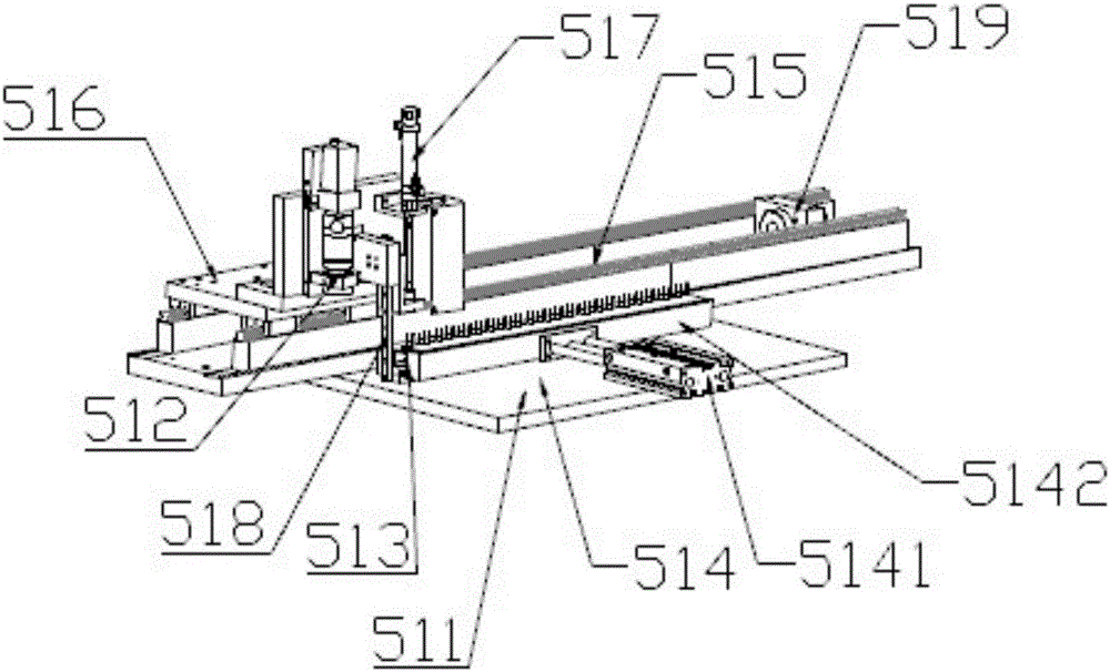
[0045] On the basis of embodiment 1, see image 3 Shown is a schematic structural view of the backstitch detection assembly 5 of this embodiment, including a backstitch detection device 51 and a picking device 52, the backstitch detection device 51 includes a base 511, a CCD camera 512 is arranged above the base 511, and a There is a carrier groove 513, and the carrier groove 513 is provided with a retaining device 514. The retaining device 514 includes a power cylinder 5141, and the power cylinder 5141 is connected with a retaining strip 5142. The base 511 is provided with a track groove 515, and the track groove 515 is Mobile platform 516 is provided, CCD camera 512 is provided with on mobile platform 516, and vertical cylinder 517 is also arranged on mobile platform 516, and vertical cylinder 517 is connected with push bar 518, and track groove 515 is provided with induction block 519, and track groove 515 An anchor point is set.


PUM


Abstract

The invention belongs to the field of production of medical apparatus, and particularly relates to a single-wing intravenous needle assembling machine. The single-wing intravenous needle assembling machine comprises a wing charging device (1) for positioning a wing into a carrier (13); starting with the wing charging device (1), a needle charging assembly (2) is connected to a conveyor belt at the back of the wing charging device (1); a right-angle conveying assembly (3) is connected to a conveyor belt at the back of the needle charging device (2); an oven (4) is connected to a conveyor belt at the back of the right-angle conveying assembly (3); a return needle detecting assembly (5) is connected to a conveyor belt at the back of the oven (4); a first air testing device (7) is connected to a conveyor belt at the back of the return needle detecting assembly (5); a carrier reversing device (6) is arranged at the back of the first air testing device (7). With the adoption of the single-wing intravenous needle assembling machine, a single-wing intravenous needle is hardly attached with bacteria during being assembled, so that the safety is high; in addition, the single-wing intravenous needle assembling machine is high in automation degree, so that the assembling efficiency can be greatly improved, and mass production can be achieved; the whole design of the single-wing intravenous needle assembling machine is reasonable, and the structure is simple.

Description

technical field [0001] The invention belongs to the field of medical equipment production, in particular to a single-wing venous needle assembly machine. Background technique [0002] The single-wing venous needle assembly machine is a medical device used for human injection. In order to ensure the hygiene and safety of the injection, it is necessary to ensure that the single-wing venous needle assembly of the infusion set is not polluted during the production process. However, the current single-winged venous needle assembly machine usually completes the assembly and processing of venous needle components by manual assembly or a combination of manual assembly and equipment assembly. It is easy to attach germs during the packaging process, which is not safe enough. In addition, manual packaging is more efficient. Low, not conducive to mass production, the overall design is not reasonable enough, poor practicability. [0003] In order to improve the existing technology, peop...

Claims


Application Information

Patent Timeline
Patent Type & Authority Applications(China)
IPC IPC(8): B23P21/00
CPCB23P21/004
Inventor 梁启明
Owner 梁启明
Why Eureka
Try Eureka